

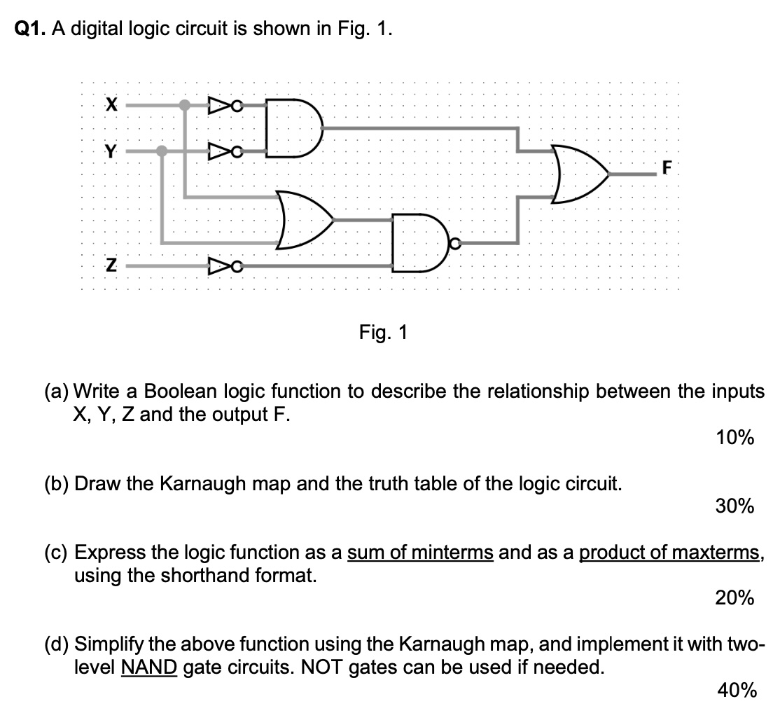
Question: Q 1 . A digital logic circuit is shown in Fig. 1 . Fig. 1 ( a ) Write a Boolean logic function to describe
Q A digital logic circuit is shown in Fig.
Fig.
a Write a Boolean logic function to describe the relationship between the inputs X Y Z and the output F
b Draw the Karnaugh map and the truth table of the logic circuit.
c Express the logic function as a sum of minterms and as a product of maxterms, using the shorthand format.
d Simplify the above function using the Karnaugh map, and implement it with twolevel NAND gate circuits. NOT gates can be used if needed.
Step by Step Solution
There are 3 Steps involved in it
1 Expert Approved Answer
Step: 1 Unlock

Question Has Been Solved by an Expert!
Get step-by-step solutions from verified subject matter experts
Step: 2 Unlock
Step: 3 Unlock