

Question: Q 1 . For the circuit shown below, prepare the straight line bode plot for the magnitude of T ( j w ) . Carefully
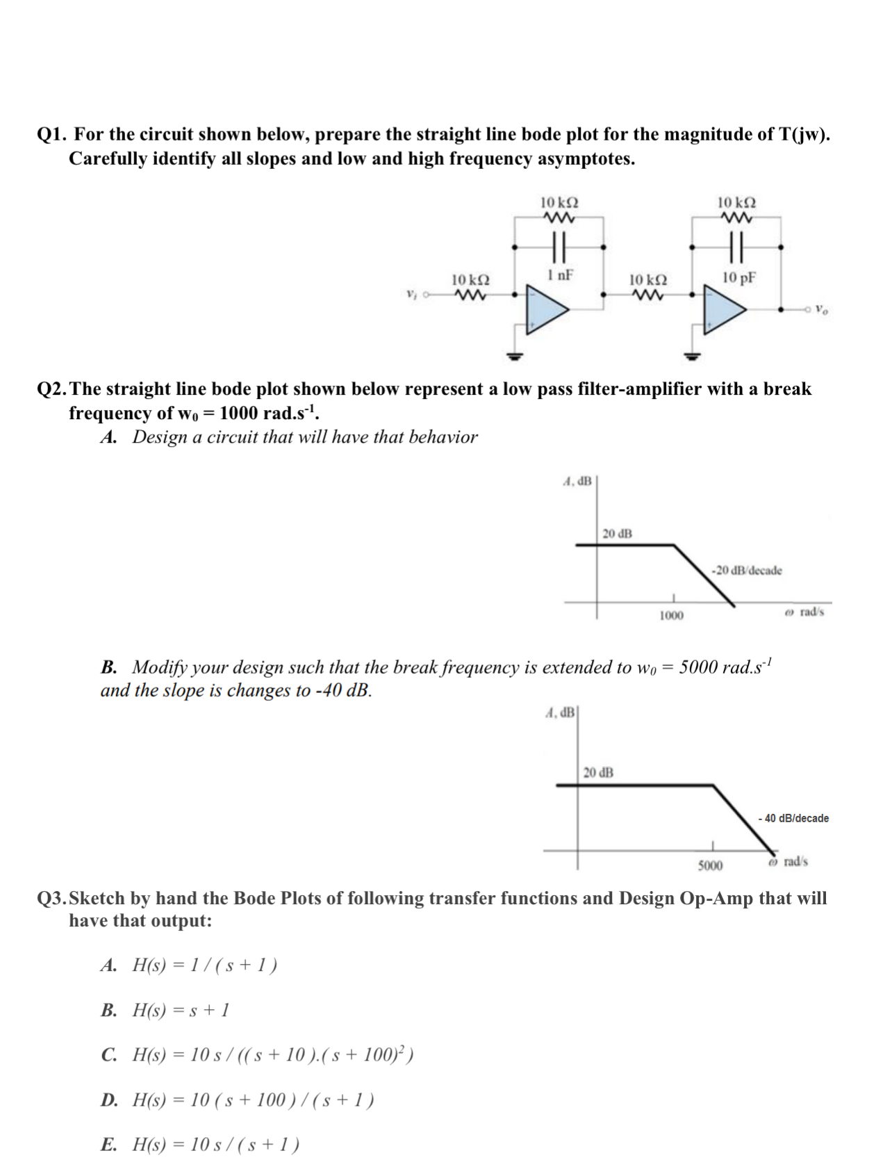
Q For the circuit shown below, prepare the straight line bode plot for the magnitude of Carefully identify all slopes and low and high frequency asymptotes.
Q The straight line bode plot shown below represent a low pass filteramplifier with a break frequency of rad.
A Design a circuit that will have that behavior
B Modify your design such that the break frequency is extended to rad. and the slope is changes to dB
Q Sketch by hand the Bode Plots of following transfer functions and Design OpAmp that will have that output:
A
B
C
D
E
Step by Step Solution
There are 3 Steps involved in it
1 Expert Approved Answer
Step: 1 Unlock

Question Has Been Solved by an Expert!
Get step-by-step solutions from verified subject matter experts
Step: 2 Unlock
Step: 3 Unlock