

Question: Q 1 ) Posture Analysis: a . Numerical solution of position variables: Write a computer program to solve the unknowns using the Newton - Raphson
Q Posture Analysis:
a Numerical solution of position variables: Write a computer program to solve the
unknowns using the NewtonRaphson technique.
Your written work must legibly show all the intermediate steps, such as
the cartesian components of the equations, Jacobian, etc.
Run your program to calculate the position variables against the input
angle for all the links Rotation of links and ; and Xcoordinate of
link
Present your numerical results for each link both in tabular format and as
graphs. Discretize the range of input angle with deg and show your results
for each input angle.
b Expand your vector loop solution to capture the motion of points B P coupler
point and C
i Determine the stroke of the piston Link
ii Determine the total distance travelled by C for a single rotation of the
input link.
iii. Plot the locus of the coupler point P XY plot for a complete rotation of
the input link.
iv Calculate the input posture when the coupler point P has the maximum X
and Y displacements and the minimum X and Y displacements.
Q Velocity and Acceleration Analysis.
a Kinematic coefficients
i Differentiate your vector loop equations to determine the firstorder and
secondorder kinematic coefficients of the mechanism. Show your work.
ii Calculate these coefficients for each input angle using a computer code.
Present your numerical results for each link both in tabular format and as
graphs. Discretize the range of input angle with deg and show your results
for each input angle.
iii. Show the instant centers on a scaled drawing of the mechanism for two
input angles. Determine the firstorder kinematic coefficients using
instant centers for those two input angles. Verify the accuracy of your
computer code by comparing the answer to this question to the values
calculated in part ii
b Plot the angular velocities and accelerations of links and and the linear velocity
and accelerations of point C and Link against the input posture. Present your
numerical results for each link both in tabular format and as graphs. Discretize the
range of input angle with deg and show your results for each input angle.
c Velocity of point P
i Determine the firstorder and secondorder kinematic coefficient of point
P Present your numerical results both in tabular format and as graphs.
Discretize the range of input angle with deg and show your results for each
input angle.
ii Plot the velocity and acceleration of point P against the input angle.
Present your numerical results both in tabular format and as graphs.
Discretize the range of input angle with deg and show your results for each
input angle.
Q Static Force Analysis of the Mechanism
a Draw free body diagrams of links and Identify the type of members for
these links two force, two force with a moment, three force, three force with a
moment, four force, etc.
b Perform a manual graphical static force analysis for one posture of the input link.
Ensure that the analysis is performed on an accurately scaled drawing of the
mechanism. For the initial iteration neglect the effects of gravity. Then for the final
iteration include the effects of gravity. Comment on the significance of gravity.
I WILL GIVE YOU GOOD REVIEW IF SOLVED CORRECTLY.
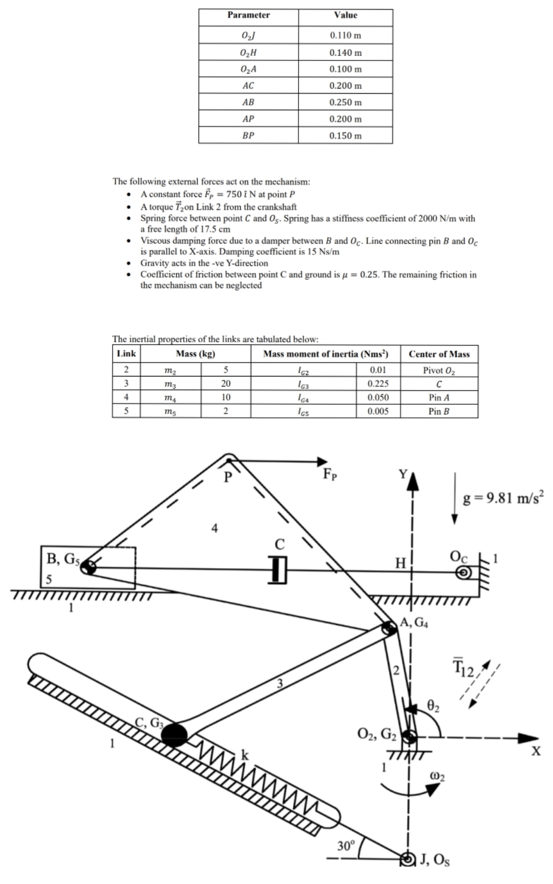
tableParameterValue m m m m m m m
The following external forces act on the mechanism:
A constant force vechat at point
A torque vec on Link from the crankshaft
Spring force between point and Spring has a stiffness coefficient of with a free length of cm
Viscous damping force due to a damper between and Line connecting pin and is parallel to Xaxis. Damping coefficient is
Gravity acts in the ve Ydirection
Coefficient of friction between point C and ground is The remaining friction in the mechanism can be neglected
The inertial properties of the links are tabulated below:
tableLinkMass kgMass moment of inertia Nms Center of MassPivot
Step by Step Solution
There are 3 Steps involved in it
1 Expert Approved Answer
Step: 1 Unlock

Question Has Been Solved by an Expert!
Get step-by-step solutions from verified subject matter experts
Step: 2 Unlock
Step: 3 Unlock