

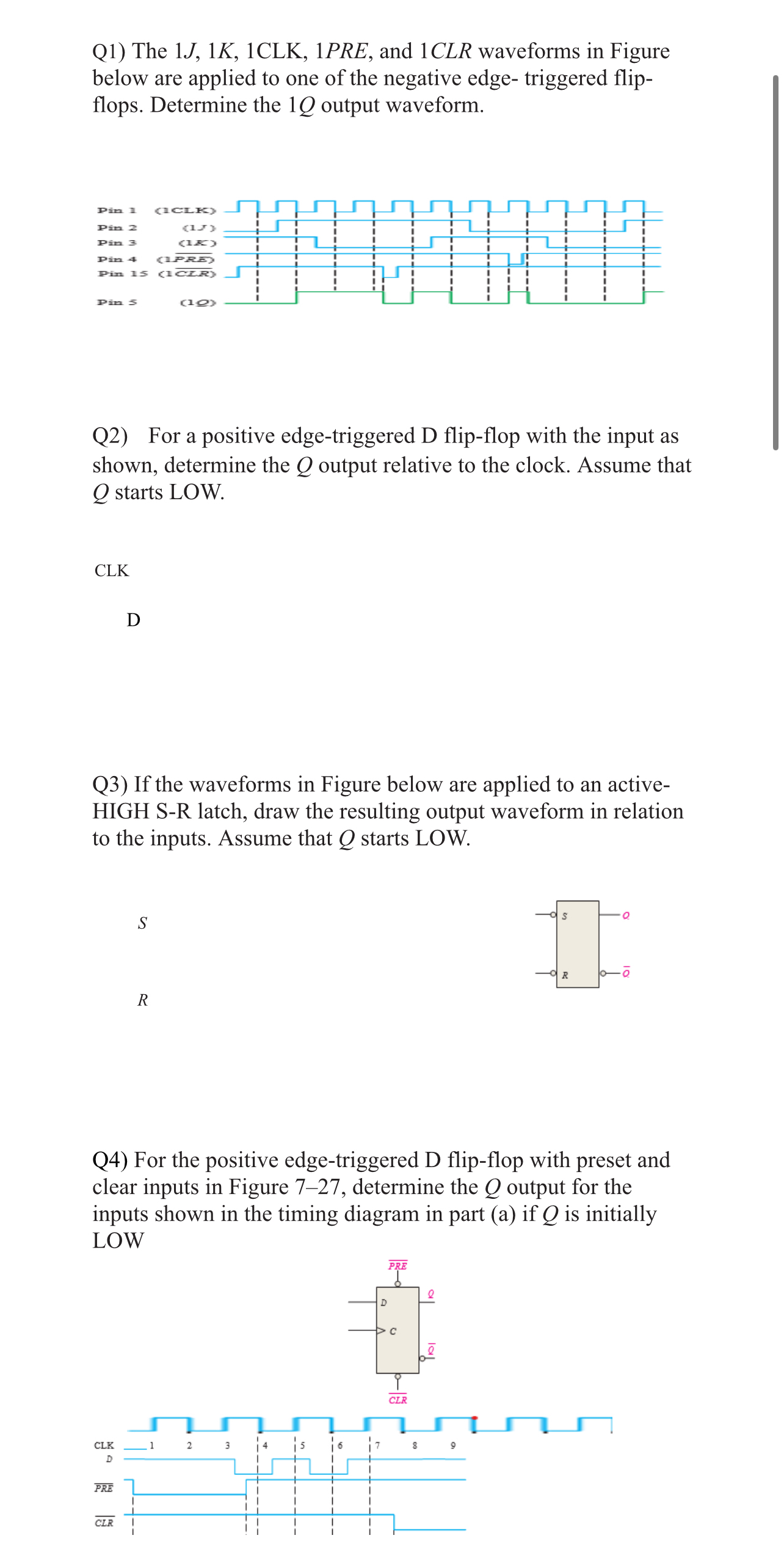
Question: Q 1 ) The 1 J , 1 K , 1 C L K , 1 PRE, and 1 C L R waveforms in Figure
Q The PRE, and waveforms in Figure below are applied to one of the negative edge triggered flipflops. Determine the output waveform.
Q For a positive edgetriggered D flipflop with the input as shown, determine the output relative to the clock. Assume that starts LOW.
CLK
D
Q If the waveforms in Figure below are applied to an activeHIGH SR latch, draw the resulting output waveform in relation to the inputs. Assume that starts LOW.
S
R
Q For the positive edgetriggered D flipflop with preset and clear inputs in Figure determine the output for the inputs shown in the timing diagram in part a if is initially LOW
Step by Step Solution
There are 3 Steps involved in it
1 Expert Approved Answer
Step: 1 Unlock

Question Has Been Solved by an Expert!
Get step-by-step solutions from verified subject matter experts
Step: 2 Unlock
Step: 3 Unlock