

Question: Q 1 ) The system shown in fig 1 is used to monitor the temperature of a chamber. The temperature is measured through a sensor
Q The system shown in fig is used to monitor the temperature of a chamber.
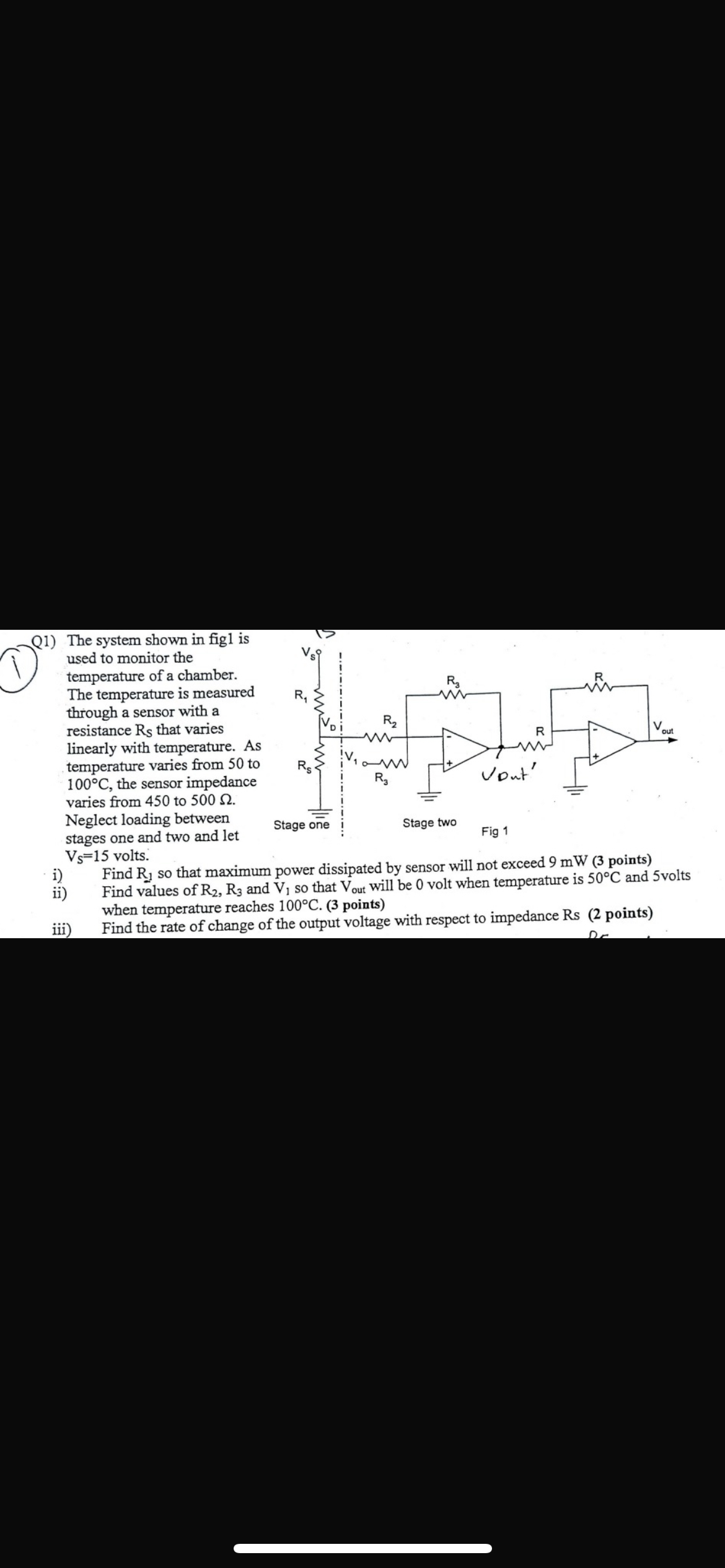
The temperature is measured through a sensor with a resistance that varies linearly with temperature. As temperature varies from to the sensor impedance varies from to Neglect loading between stages one and two and let
s
volts.
i Find so that maximum power dissipated by sensor will not exceed mW points
ii Find values of and so that will be volt when temperature is and volts when temperature reaches points
iii Find the rate of change of the output voltage with respect to impedance Rs points
Step by Step Solution
There are 3 Steps involved in it
1 Expert Approved Answer
Step: 1 Unlock

Question Has Been Solved by an Expert!
Get step-by-step solutions from verified subject matter experts
Step: 2 Unlock
Step: 3 Unlock