

Question: Q 2 . Shown in Fig. Q 2 is part of the electrical schematic for a building, with relevant parameters of the supply circuit and
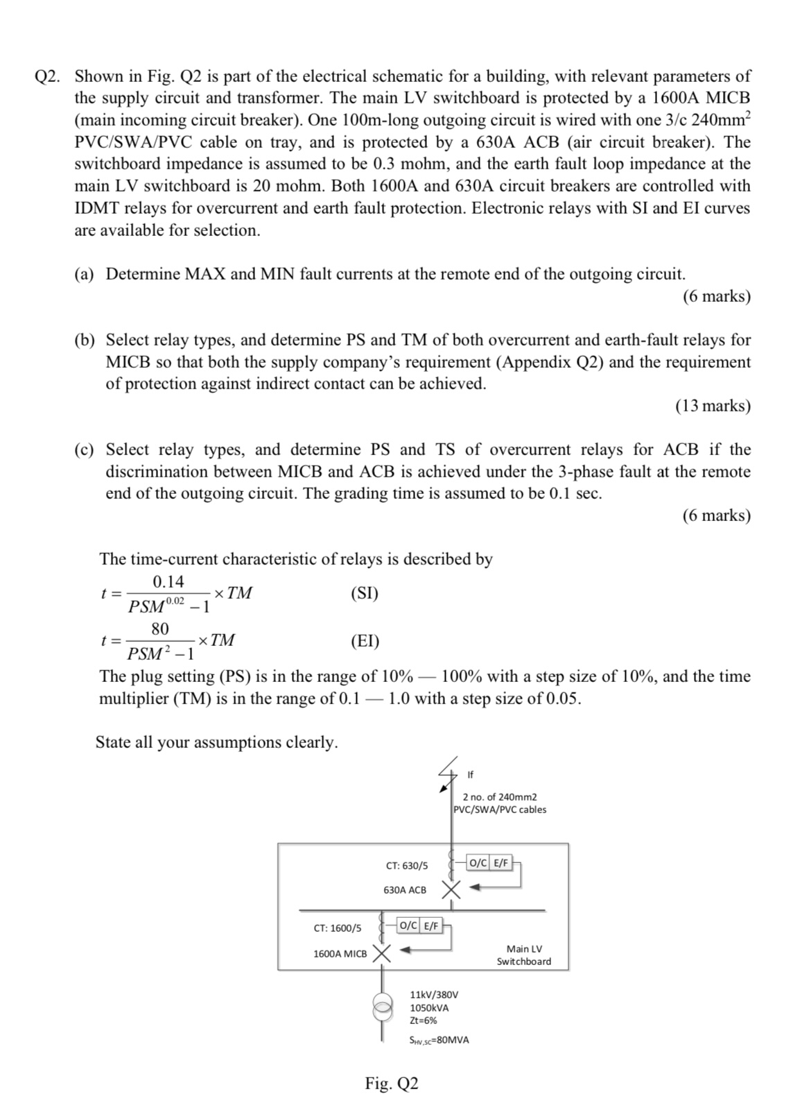
Q Shown in Fig. Q is part of the electrical schematic for a building, with relevant parameters of the supply circuit and transformer. The main LV switchboard is protected by a A MICB main incoming circuit breaker One m long outgoing circuit is wired with one PVCSWAPVC cable on tray, and is protected by a A ACB air circuit breaker The switchboard impedance is assumed to be mohm, and the earth fault loop impedance at the main LV switchboard is mohm. Both A and A circuit breakers are controlled with IDMT relays for overcurrent and earth fault protection. Electronic relays with SI and EI curves are available for selection.
a Determine MAX and MIN fault currents at the remote end of the outgoing circuit.
marks
b Select relay types, and determine PS and TM of both overcurrent and earthfault relays for MICB so that both the supply company's requirement Appendix Q and the requirement of protection against indirect contact can be achieved.
marks
c Select relay types, and determine PS and TS of overcurrent relays for ACB if the discrimination between MICB and ACB is achieved under the phase fault at the remote end of the outgoing circuit. The grading time is assumed to be sec
marks
The timecurrent characteristic of relays is described by
The plug setting PS is in the range of with a step size of and the time multiplier TM is in the range of with a step size of
State all your assumptinns clearly
Step by Step Solution
There are 3 Steps involved in it
1 Expert Approved Answer
Step: 1 Unlock

Question Has Been Solved by an Expert!
Get step-by-step solutions from verified subject matter experts
Step: 2 Unlock
Step: 3 Unlock