

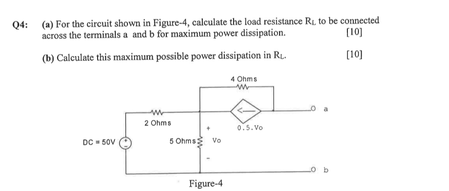
Question: Q 4 : ( a ) For the circuit shown in Figure - 4 , calculate the load resistance R L to be connected across
Q: a For the circuit shown in Figure calculate the load resistance to be connected across the terminals a and for maximum power dissipation.
b Calculate this maximum possible power dissipation in
Step by Step Solution
There are 3 Steps involved in it
1 Expert Approved Answer
Step: 1 Unlock

Question Has Been Solved by an Expert!
Get step-by-step solutions from verified subject matter experts
Step: 2 Unlock
Step: 3 Unlock