

Question: Q 4 . Root locus design. Consider the control system strown in the figure below. 2 5 points It is desired to design the P
Q Root locus design.
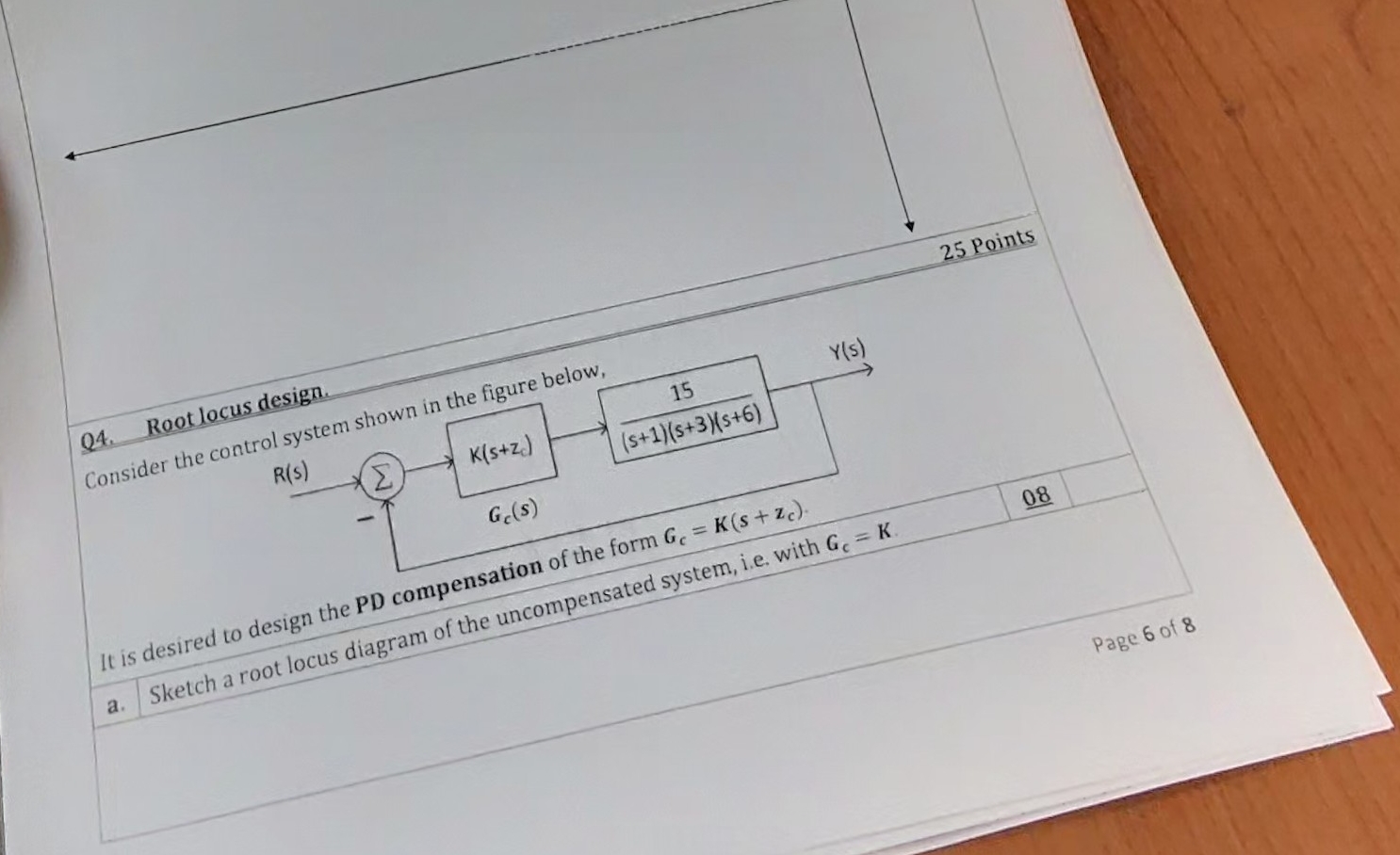
Consider the control system strown in the figure below.
points
It is desired to design the compensation of the form
a Sketch a root locus diagram of the uncompensated system, ie with
Page
Spm j Calculate the angleb. For the compensated closedloop system, Le with G Ks z the desiredpoles are atdominantcompensation zero using the phase angle condition. Sketch a neat explainingdiagram and show all the necessary calculationsPage of
Q Root locus design.
Consider the control system shown in the figure below.
It is desired to design the PD compensation of the form
a Sketch a root locus diagram of the uncompensated system, ie with
Page
Step by Step Solution
There are 3 Steps involved in it
1 Expert Approved Answer
Step: 1 Unlock

Question Has Been Solved by an Expert!
Get step-by-step solutions from verified subject matter experts
Step: 2 Unlock
Step: 3 Unlock