

Question: Q 4 . The Figure below shows a drilling process that needs to be controlled using PLC . The sequence of operation - the function
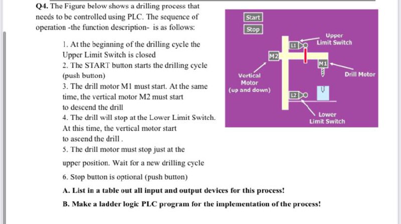
Q The Figure below shows a drilling process that needs to be controlled using PLC The sequence of operation the function description is as follows:
At the beginning of the drilling cycle the Upper Limit Switch is closed
The START button starts the drilling cycle push button
The drill motor M must start. At the same time, the vertical motor M must start
to descend the drill
The drill will stop at the Lower Limit Switch.
At this time, the vertical motor start to ascend the drill
The drill motor must stop just at the upper position. Wait for a new drilling cycle
Stop button is optional push button
A List in a table out all input and output devices for this process!
B Make a ladder logic PLC program for the implementation of the process!
Step by Step Solution
There are 3 Steps involved in it
1 Expert Approved Answer
Step: 1 Unlock

Question Has Been Solved by an Expert!
Get step-by-step solutions from verified subject matter experts
Step: 2 Unlock
Step: 3 Unlock