

Question: Q 7 . a . For the circuit shown in Figure Q 7 i . Find the value of the total impedance Z T and
Q
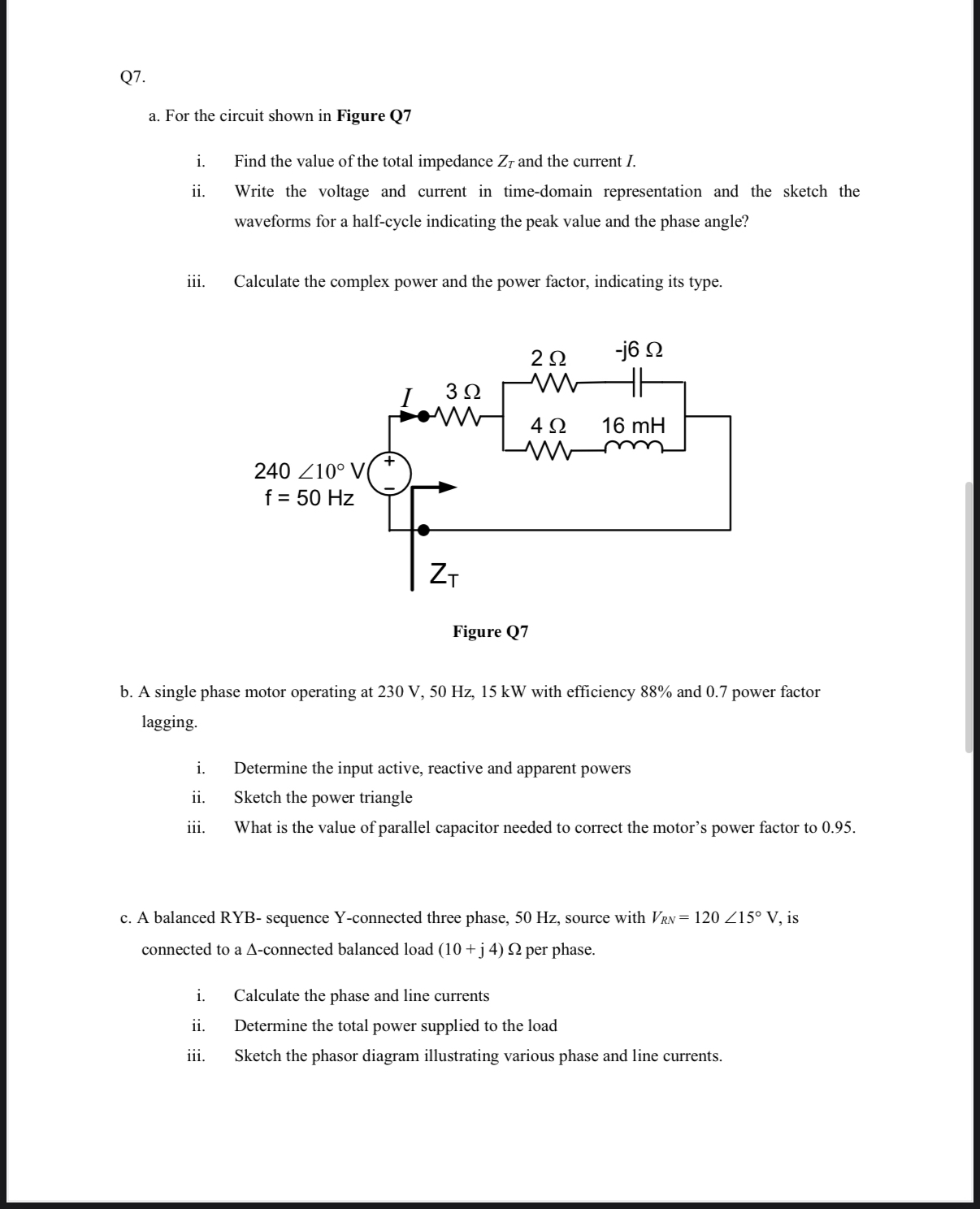
a For the circuit shown in Figure Q
i Find the value of the total impedance and the current I.
ii Write the voltage and current in timedomain representation and the sketch the waveforms for a halfcycle indicating the peak value and the phase angle?
iii. Calculate the complex power and the power factor, indicating its type.
Figure Q
b A single phase motor operating at with efficiency and power factor lagging.
i Determine the input active, reactive and apparent powers
ii Sketch the power triangle
iii. What is the value of parallel capacitor needed to correct the motor's power factor to
c A balanced RYB sequence Yconnected three phase, Hz source with is connected to a connected balanced load per phase.
i Calculate the phase and line currents
ii Determine the total power supplied to the load
iii. Sketch the phasor diagram illustrating various phase and line currents.
Step by Step Solution
There are 3 Steps involved in it
1 Expert Approved Answer
Step: 1 Unlock

Question Has Been Solved by an Expert!
Get step-by-step solutions from verified subject matter experts
Step: 2 Unlock
Step: 3 Unlock