Question: Q Nae OO ale SoS Scannable Document NAME __ PLANE MIRRORS PERIOD DATE EXPERIMENT 2 a According to the laws of reflection, (1) the incident
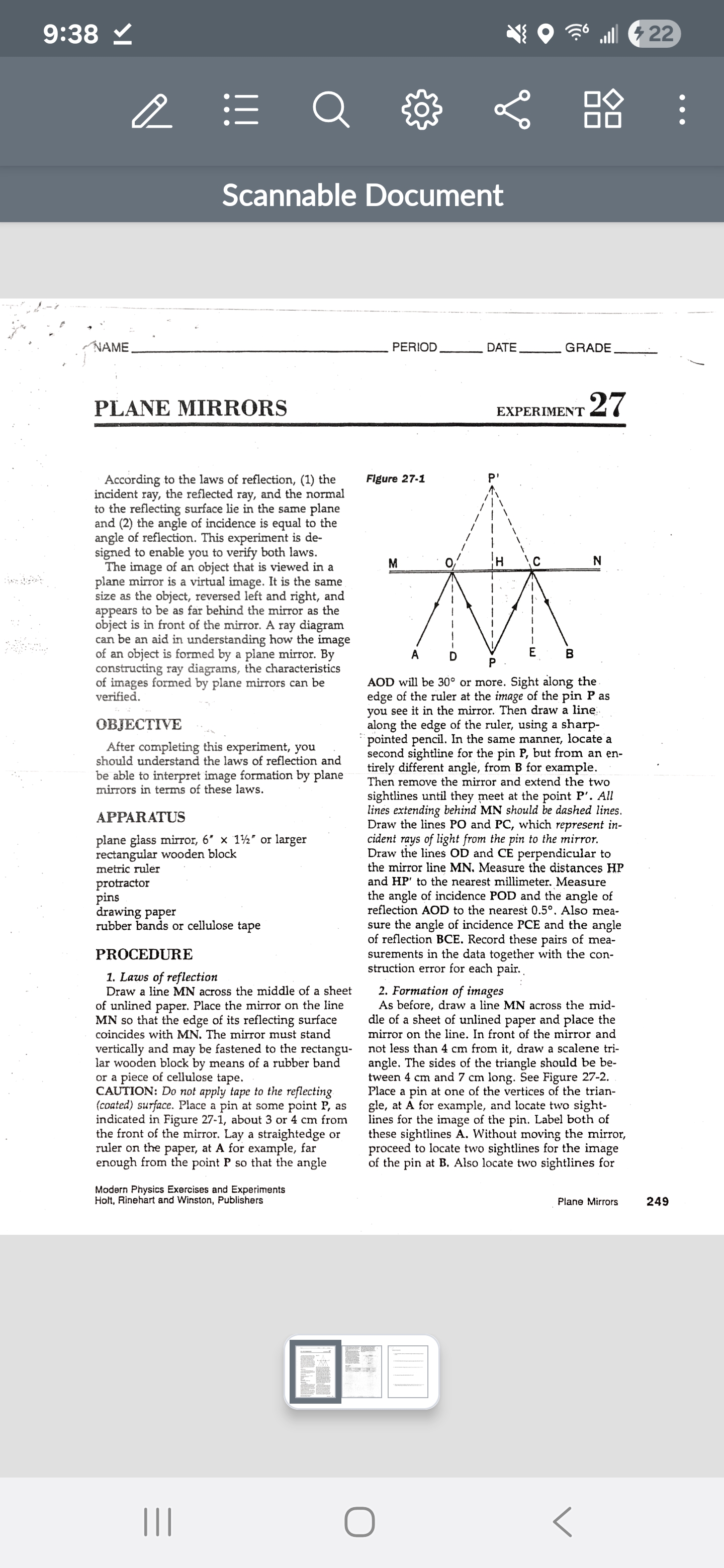
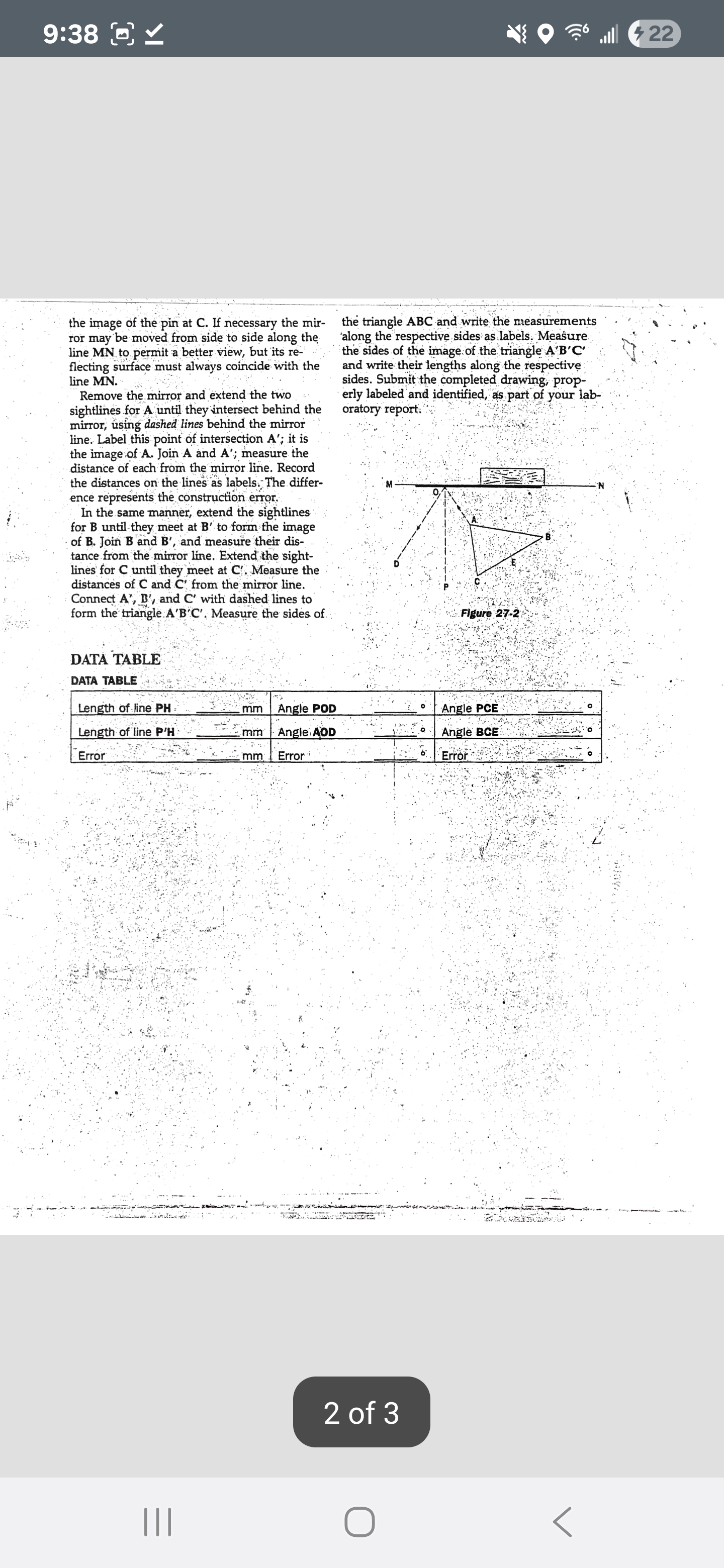
Q Nae OO ale SoS Scannable Document NAME __ PLANE MIRRORS PERIOD DATE EXPERIMENT 2 a According to the laws of reflection, (1) the incident ray, the reflected ray, and the normal to the reflecting surface lie in the same plane and (2) the angle of incidence is equal to the angle of reflection. This experiment is de- signed to enable you to verify both laws. The image of an object that is viewed in a plane mirror is a virtual image. It is the same size as the object, reversed left and right, and appears to be as far behind the mirror as the object is in front of the mirror. A ray diagram can be an aid in understanding how the image of an object is formed by a plane mirror. By constructing ray diagrams, the characteristics of images formed by plane mirrors can be verified. OBJECTIVE After completing this experiment, you should understand the laws of reflection and be able to interpret image formation by plane mirrors in terms of these laws. APPARATUS plane glass mirror, 6" x 1%" or larger rectangular wooden block metric ruler protractor pins drawing paper rubber bands or cellulose tape PROCEDURE 1, Laws of reflection Draw a line MN across the middle of a sheet of unlined paper. Place the mirror on the line MN so that the edge of its reflecting surface coincides with MN. The mirror must stand vertically and may be fastened to the rectangu- lar wooden block by means of a rubber band or a piece of cellulose tape. CAUTION: Do not apply tape to the reflecting (coated) surface. Place a pin at some point P, as indicated in Figure 27-1, about 3 or 4 cm from the front of the mirror. Lay a straightedge or ruler on the paper, at A for example, far enough from the point P so that the angle Modern Physics Exercises and Experiments Holt, Rinehart and Winston, Publishers Figure 27-1 Pp' A D P E B AOD will be 30 or more. Sight along the edge of the ruler at the image of the pin P as you see it in the mirror. Then draw a line along the edge of the ruler, using a sharp- * pointed pencil. In the same manner, locate a second sightline for the pin P, but from an en- tirely different angle, from B for example. Then remove the mirror and extend the two sightlines until they meet at the point P'. All lines extending behind MN should be dashed lines. Draw the lines PO and PC, which represent in- cident rays of light from the pin to the mirror. Draw the lines OD and CE perpendicular to the mirror line MN. Measure the distances HP and HP' to the nearest millimeter. Measure the angle of incidence POD and the angle of reflection AOD to the nearest 0.5. Also mea- sure the angle of incidence PCE and the angle of reflection BCE. Record these pairs of mea- surements in the data together with the con- struction error for each pair. 2. Formation of images As before, draw a line MN across the mid- dle of a sheet of unlined paper and place the mirror on the line. In front of the mirror and not less than 4 cm from it, draw a scalene tri- angle. The sides of the triangle should be be- tween 4 cm and 7 cm long. See Figure 27-2. Place a pin at one of the vertices of the trian- gle, at A for example, and locate two sight- lines for the image of the pin. Label both of these sightlines A. Without moving the mirror, proceed to locate two sightlines for the image of the pin at B. Also locate two sightlines for Plane Mirrors GRADE____ 9:38 [) _ the image of the pin at C. If necessary the mir- the triangle ABC and write the measurements ror may be moved from side to side along the along the respective sides as labels. Measure line MN to permit a better view, but its re- the sides of the image of the triangle A'B'C' flecting surface must always coincide with the and write their lengths along the respective line MN. sides. Submit the completed drawing, prop- Remove the mirror and extend the two erly labeled and identified, as part of your lab- sightlines for A until they intersect behind the oratory report." mirror, using dashed lines behind the mirror line. Label this point of intersection A'; it is the image of A. Join A and A'; measure the distance of each from the mirror line. Record the distances on the lines as labels. The differ- ence represents the construction error. In the same manner, extend the sightlines for B until they meet at B' to form the image of B. Join B and B', and measure their dis- tance from the mirror line. Extend the sight- lines for C until they meet at C'. Measure the distances of C and C' from the mirror line. Connect A', B', and C' with dashed lines to form the triangle A'B'C'. Measure the sides of Figure 27-2 DATA TABLE DATA TABLE Length of line PH mm Angle POD Angle PCE Length of line P'H - 2 mm Angle AOD Angle BCE "Error mm Error Error 2 of 3 Ost | Reflection Lab Questions 1.) Using you observations, what can you conclude about the angle of incidence and the angle of reflection? (Level 1) 2.) How far behind the plane mirror is the image of an object that is located in front of the mirror? (Level 1) 3.) What are the characteristics of images formed by a plane mirror (size. orientation. location)? (Level 2) 4.) Why is a plane mirror image called virtual rather than real? (Level 2) 5.) What were causes of error in you distance of the image as opposed to the actual distance of the mirror from the object? What would give a better distance result, a thick or a thin mirror? Explain. (Level 3) lI O <
Step by Step Solution
There are 3 Steps involved in it
1 Expert Approved Answer
Step: 1 Unlock
Question Has Been Solved by an Expert!
Get step-by-step solutions from verified subject matter experts
Step: 2 Unlock
Step: 3 Unlock
Students Have Also Explored These Related Accounting Questions!