

Question: Q1: Using Logixpro software to draw ladder logic program with proper addresses with the following specifications: a. Limit switch connected to terminal screw 4 of
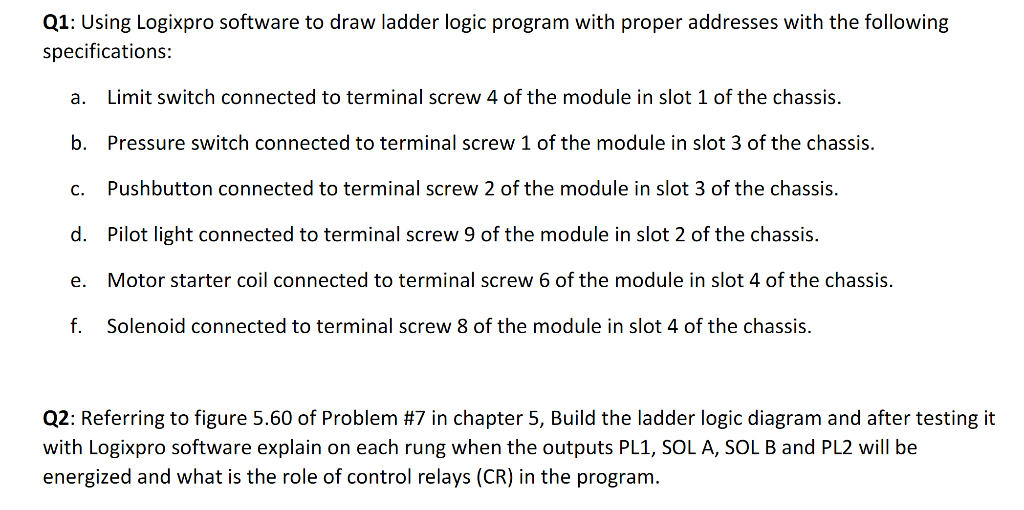
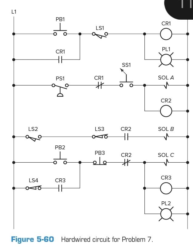
Q1: Using Logixpro software to draw ladder logic program with proper addresses with the following specifications: a. Limit switch connected to terminal screw 4 of the module in slot 1 of the chassis. b. Pressure switch connected to terminal screw 1 of the module in slot 3 of the chassis. C. Pushbutton connected to terminal screw 2 of the module in slot 3 of the chassis. d. Pilot light connected to terminal screw 9 of the module in slot 2 of the chassis. e. Motor starter coil connected to terminal screw 6 of the module in slot 4 of the chassis. f. Solenoid connected to terminal screw 8 of the module in slot 4 of the chassis. Q2: Referring to figure 5.60 of Problem #7 in chapter 5, Build the ladder logic diagram and after testing it with Logixpro software explain on each rung when the outputs PL1, SOLA, SOL B and PL2 will be energized and what is the role of control relays (CR) in the program. L1 PB1 I CR1 LS1 PL1 CR1 HE SS1 PS1 SOL A CR1 H CR2 LS2 LS3 SOL B CR2 HE PB2 PB3 SOLC olo CR2 H CR3 LS4 CR3 HE PL2 Figure 5-60 Hardwired circuit for Problem 7. Q1: Using Logixpro software to draw ladder logic program with proper addresses with the following specifications: a. Limit switch connected to terminal screw 4 of the module in slot 1 of the chassis. b. Pressure switch connected to terminal screw 1 of the module in slot 3 of the chassis. C. Pushbutton connected to terminal screw 2 of the module in slot 3 of the chassis. d. Pilot light connected to terminal screw 9 of the module in slot 2 of the chassis. e. Motor starter coil connected to terminal screw 6 of the module in slot 4 of the chassis. f. Solenoid connected to terminal screw 8 of the module in slot 4 of the chassis. Q2: Referring to figure 5.60 of Problem #7 in chapter 5, Build the ladder logic diagram and after testing it with Logixpro software explain on each rung when the outputs PL1, SOLA, SOL B and PL2 will be energized and what is the role of control relays (CR) in the program. L1 PB1 I CR1 LS1 PL1 CR1 HE SS1 PS1 SOL A CR1 H CR2 LS2 LS3 SOL B CR2 HE PB2 PB3 SOLC olo CR2 H CR3 LS4 CR3 HE PL2 Figure 5-60 Hardwired circuit for Problem 7
Step by Step Solution
There are 3 Steps involved in it

Get step-by-step solutions from verified subject matter experts