

Question: Q2. [20 marks) The shown PIC16F84A program is used to generate a square wave on all pins of PORTB using the TMRO module. Carefully read
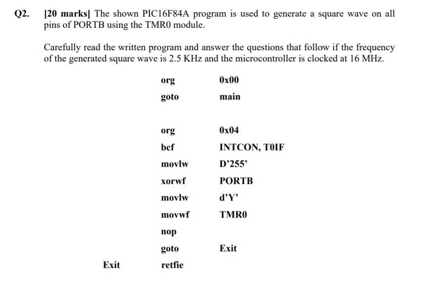
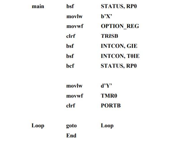

Q2. [20 marks) The shown PIC16F84A program is used to generate a square wave on all pins of PORTB using the TMRO module. Carefully read the written program and answer the questions that follow if the frequency of the generated square wave is 2.5 KHz and the microcontroller is clocked at 16 MHz. 0x00 org goto main Ox04 org bef INTCON, TOIF D'255 movlw xorwf PORTB d'Y' movlw movwf TMRO nop goto Exit Exit retfie main bsf STATUS, RPO b'X movlw movwf clrf bsf OPTION_REG TRISB INTCON, GIE INTCON, TOIE STATUS, RPO bsf bcf d'Y movlw movwf clrf TMRO PORTB Loop goto Loop End b. [10 marks] Update your setting from question (a) to accurately generate the required signal (i.e., find the exact correct value for Y to take account of extra consumed instruction cycles around and inside the interrupt service routine). Q2. [20 marks) The shown PIC16F84A program is used to generate a square wave on all pins of PORTB using the TMRO module. Carefully read the written program and answer the questions that follow if the frequency of the generated square wave is 2.5 KHz and the microcontroller is clocked at 16 MHz. 0x00 org goto main Ox04 org bef INTCON, TOIF D'255 movlw xorwf PORTB d'Y' movlw movwf TMRO nop goto Exit Exit retfie main bsf STATUS, RPO b'X movlw movwf clrf bsf OPTION_REG TRISB INTCON, GIE INTCON, TOIE STATUS, RPO bsf bcf d'Y movlw movwf clrf TMRO PORTB Loop goto Loop End b. [10 marks] Update your setting from question (a) to accurately generate the required signal (i.e., find the exact correct value for Y to take account of extra consumed instruction cycles around and inside the interrupt service routine)
Step by Step Solution
There are 3 Steps involved in it

Get step-by-step solutions from verified subject matter experts