

Question: Q2: Consider the truss shown in Figure 2. Two loading cases are applied to the joints: (1) 2 kg of load applied at joint
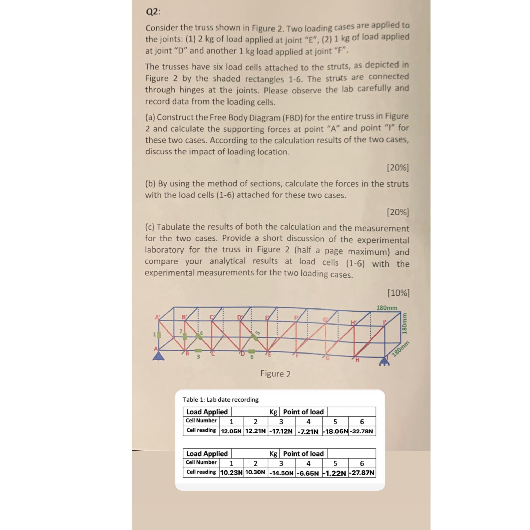
Q2: Consider the truss shown in Figure 2. Two loading cases are applied to the joints: (1) 2 kg of load applied at joint "E", (2) 1 kg of load applied at joint "D" and another 1 kg load applied at joint "F". The trusses have six load cells attached to the struts, as depicted in Figure 2 by the shaded rectangles 1-6. The struts are connected through hinges at the joints. Please observe the lab carefully and record data from the loading cells. (a) Construct the Free Body Diagram (FBD) for the entire truss in Figure 2 and calculate the supporting forces at point "A" and point "I" for these two cases. According to the calculation results of the two cases, discuss the impact of loading location. [20%] (b) By using the method of sections, calculate the forces in the struts with the load cells (1-6) attached for these two cases. [20%] (c) Tabulate the results of both the calculation and the measurement for the two cases. Provide a short discussion of the experimental laboratory for the truss in Figure 2 (half a page maximum) and compare your analytical results at load cells (1-6) with the experimental measurements for the two loading cases. [10%] A 2 S Table 1: Lab date recording Figure 2 Load Applied Kg Point of load Cell Number 1 2 3 4 5 Cell reading 12.05N 12.21N -17.12N -7.21N -18.06N-32.78N 6 Load Applied Kg Point of load 3 4 5 6 Cell Number 1 2 Cell reading 10.23N 10.30N -14.50N -6.65N -1.22N -27.87N 180mm 180mm 180mm
Step by Step Solution
There are 3 Steps involved in it

Get step-by-step solutions from verified subject matter experts