

Question: Q.2 For the step shaft shown in Figure 1, E wall at A. Forces are applied at B and C. (a) Determine the force
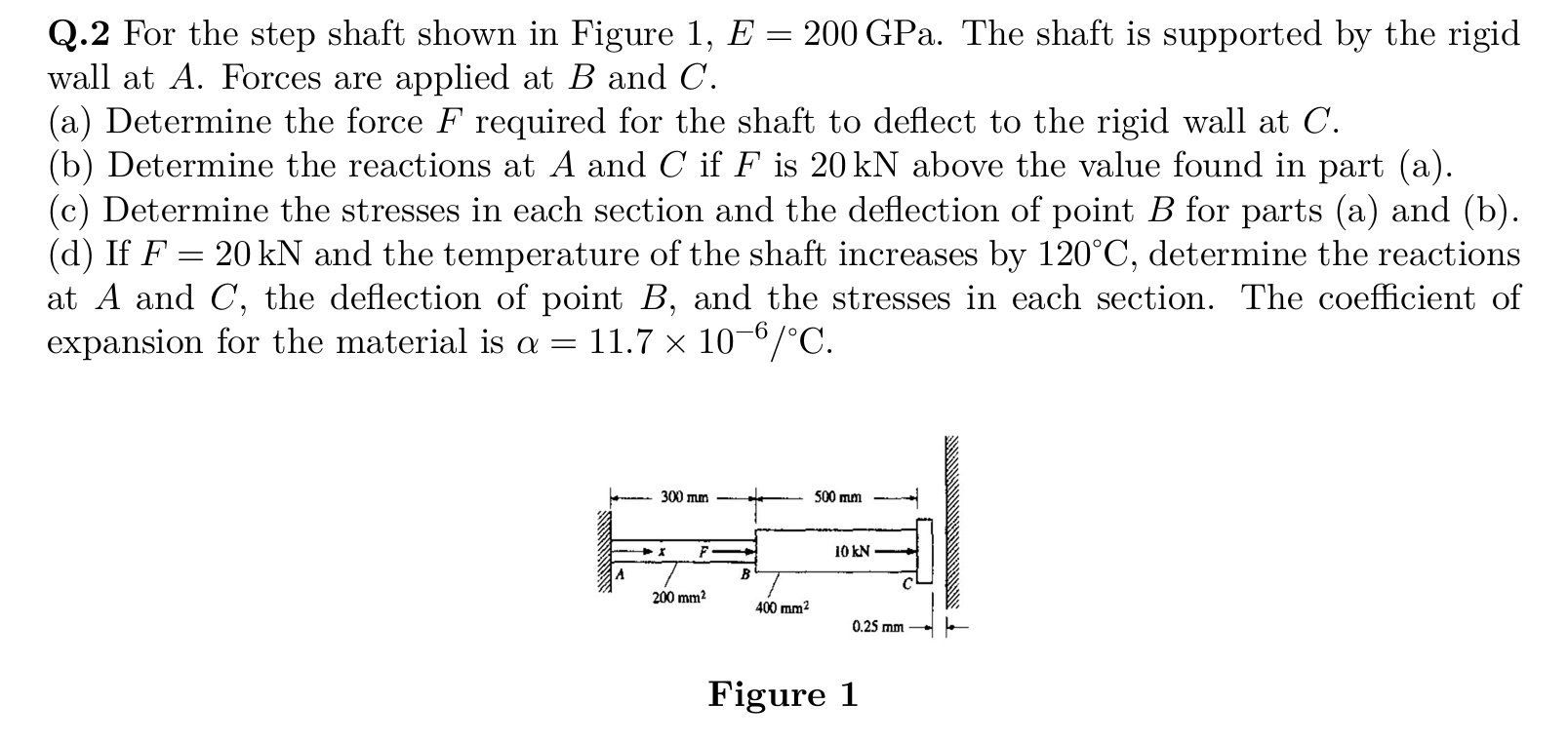
Q.2 For the step shaft shown in Figure 1, E wall at A. Forces are applied at B and C. (a) Determine the force F required for the shaft to deflect to the rigid wall at C. (b) Determine the reactions at A and C if F is 20 kN above the value found in part (a). (c) Determine the stresses in each section and the deflection of point B for parts (a) and (b). (d) If F 20 kN and the temperature of the shaft increases by 120C, determine the reactions at A and C, the deflection of point B, and the stresses in each section. The coefficient of expansion for the material is a = 11.7 10-6/C. 300 mm 200 mm B - 200 GPa. The shaft is supported by the rigid 400 mm 500 mm 10 kN 0.25 mm Figure 1
Step by Step Solution
3.41 Rating (164 Votes )
There are 3 Steps involved in it
Solutions Step 1 In this problem we are dealing with a stepped shaft subjected to applied forces at B and C and the shaft is supported by a rigid wall ... View full answer

Get step-by-step solutions from verified subject matter experts