

Question: Q2 ( You have been asked to develop a PIC MCU assembly-level program for controlling a hot air radiator. When the water is warm the
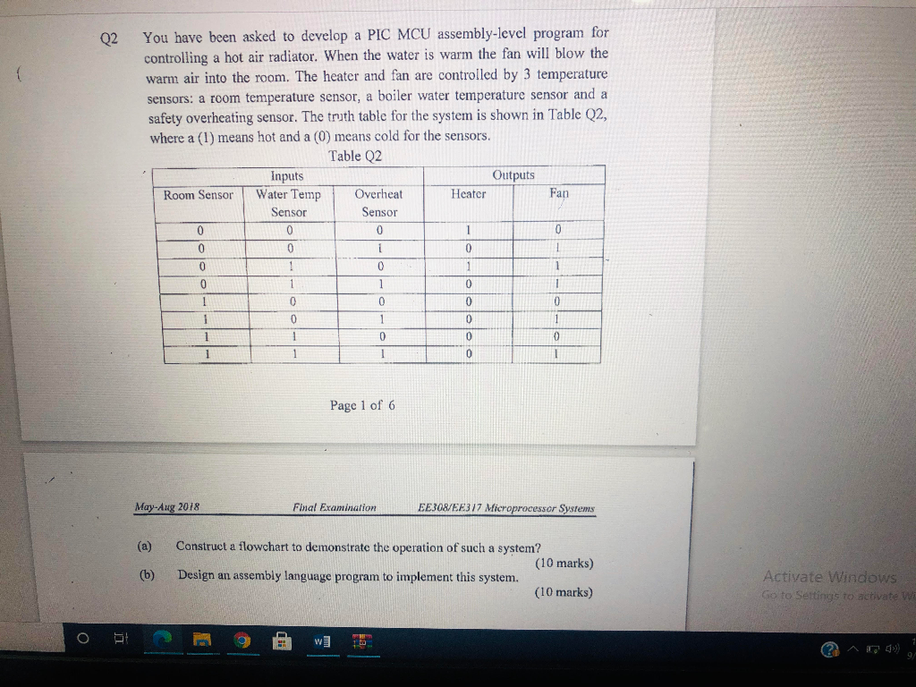
Q2 ( You have been asked to develop a PIC MCU assembly-level program for controlling a hot air radiator. When the water is warm the fan will blow the warm air into the room. The heater and fan are controlled by 3 temperature sensors: a room temperature sensor, a boiler water temperature sensor and a safety overheating sensor. The truth table for the system is shown in Table Q2, where a (1) means hot and a (0) means cold for the sensors. Table Q2 Inputs Outputs Room Sensor Water Temp Overheat Heater Fan Sensor Sensor 0 0 1 0 0 1 0 1 1 1 1 1 0 0 0 1 0 0 1 0 0 1 0 0 0 0 1 0 0 1 0 1 0 1 1 0 1 1 Page 1 of 6 May-Aug 2018 Final Examination EE308/EE317 Microprocessor Systems (a) Construct a flowchart to demonstrate the operation of such a system? (10 marks) Design an assembly language program to implement this system. (10 marks) (6) Activate Windows Go to Settings to activate w O WT 1 ta Q2 ( You have been asked to develop a PIC MCU assembly-level program for controlling a hot air radiator. When the water is warm the fan will blow the warm air into the room. The heater and fan are controlled by 3 temperature sensors: a room temperature sensor, a boiler water temperature sensor and a safety overheating sensor. The truth table for the system is shown in Table Q2, where a (1) means hot and a (0) means cold for the sensors. Table Q2 Inputs Outputs Room Sensor Water Temp Overheat Heater Fan Sensor Sensor 0 0 1 0 0 1 0 1 1 1 1 1 0 0 0 1 0 0 1 0 0 1 0 0 0 0 1 0 0 1 0 1 0 1 1 0 1 1 Page 1 of 6 May-Aug 2018 Final Examination EE308/EE317 Microprocessor Systems (a) Construct a flowchart to demonstrate the operation of such a system? (10 marks) Design an assembly language program to implement this system. (10 marks) (6) Activate Windows Go to Settings to activate w O WT 1 ta
Step by Step Solution
There are 3 Steps involved in it

Get step-by-step solutions from verified subject matter experts