

Question: QUESTION 1: (35 points) M u(t) O HR KA DC Motor Hx X(t) In the given system, the flow rate Qi is adjusted by a
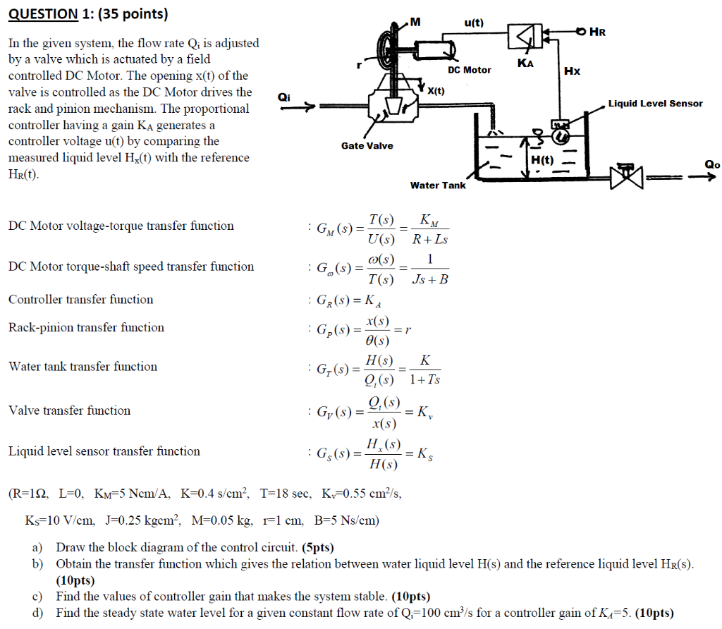
QUESTION 1: (35 points) M u(t) O HR KA DC Motor Hx X(t) In the given system, the flow rate Qi is adjusted by a valve which is actuated by a field controlled DC Motor. The opening x(t) of the valve is controlled as the DC Motor drives the rack and pinion mechanism. The proportional controller having a gain Ka generates a controller voltage u(t) by comparing the measured liquid level Hz(t) with the reference Hr(t). Liquid Level Sensor Gate Valve H(t) Qo Water Tank DC Motor voltage-torque transfer function 1 DC Motor torque-shaft speed transfer function Controller transfer function Rack-pinion transfer function T(S) KM : GM ($)= U(s) R+Ls o(s) : G(s) = T(S) Js + B : Gr(s) = KA x(s) : G(s) = =r e(s) HS) K : Gr(s) = 9,($) 1+ TS Q:(S) : Gy(s) = =K, x(s) H () :G ($)= H(S) Water tank transfer function Valve transfer function Liquid level sensor transfer function = KS (R=12, L=0, Km=5 Ncm/A, K=0.4 s/cm?, T=18 sec, K=0.55 cm/s, Ks=10 V/cm, J=0.25 kgcm?, M=0.05 kg, r=1 cm, B=5 Ns/cm) a) Draw the block diagram of the control circuit. (5pts) b) Obtain the transfer function which gives the relation between water liquid level H(s) and the reference liquid level Hr(s). (10pts) c) Find the values of controller gain that makes the system stable. (10pts) d) Find the steady state water level for a given constant flow rate of Q.=100 cm?/s for a controller gain of K1=5. (10pts) QUESTION 1: (35 points) M u(t) O HR KA DC Motor Hx X(t) In the given system, the flow rate Qi is adjusted by a valve which is actuated by a field controlled DC Motor. The opening x(t) of the valve is controlled as the DC Motor drives the rack and pinion mechanism. The proportional controller having a gain Ka generates a controller voltage u(t) by comparing the measured liquid level Hz(t) with the reference Hr(t). Liquid Level Sensor Gate Valve H(t) Qo Water Tank DC Motor voltage-torque transfer function 1 DC Motor torque-shaft speed transfer function Controller transfer function Rack-pinion transfer function T(S) KM : GM ($)= U(s) R+Ls o(s) : G(s) = T(S) Js + B : Gr(s) = KA x(s) : G(s) = =r e(s) HS) K : Gr(s) = 9,($) 1+ TS Q:(S) : Gy(s) = =K, x(s) H () :G ($)= H(S) Water tank transfer function Valve transfer function Liquid level sensor transfer function = KS (R=12, L=0, Km=5 Ncm/A, K=0.4 s/cm?, T=18 sec, K=0.55 cm/s, Ks=10 V/cm, J=0.25 kgcm?, M=0.05 kg, r=1 cm, B=5 Ns/cm) a) Draw the block diagram of the control circuit. (5pts) b) Obtain the transfer function which gives the relation between water liquid level H(s) and the reference liquid level Hr(s). (10pts) c) Find the values of controller gain that makes the system stable. (10pts) d) Find the steady state water level for a given constant flow rate of Q.=100 cm?/s for a controller gain of K1=5. (10pts)
Step by Step Solution
There are 3 Steps involved in it

Get step-by-step solutions from verified subject matter experts