

Question: Question 1 ( 4 0 marks ) Figure 1 ( a ) below shows a K truss supported with a pin at A and a
Question marks
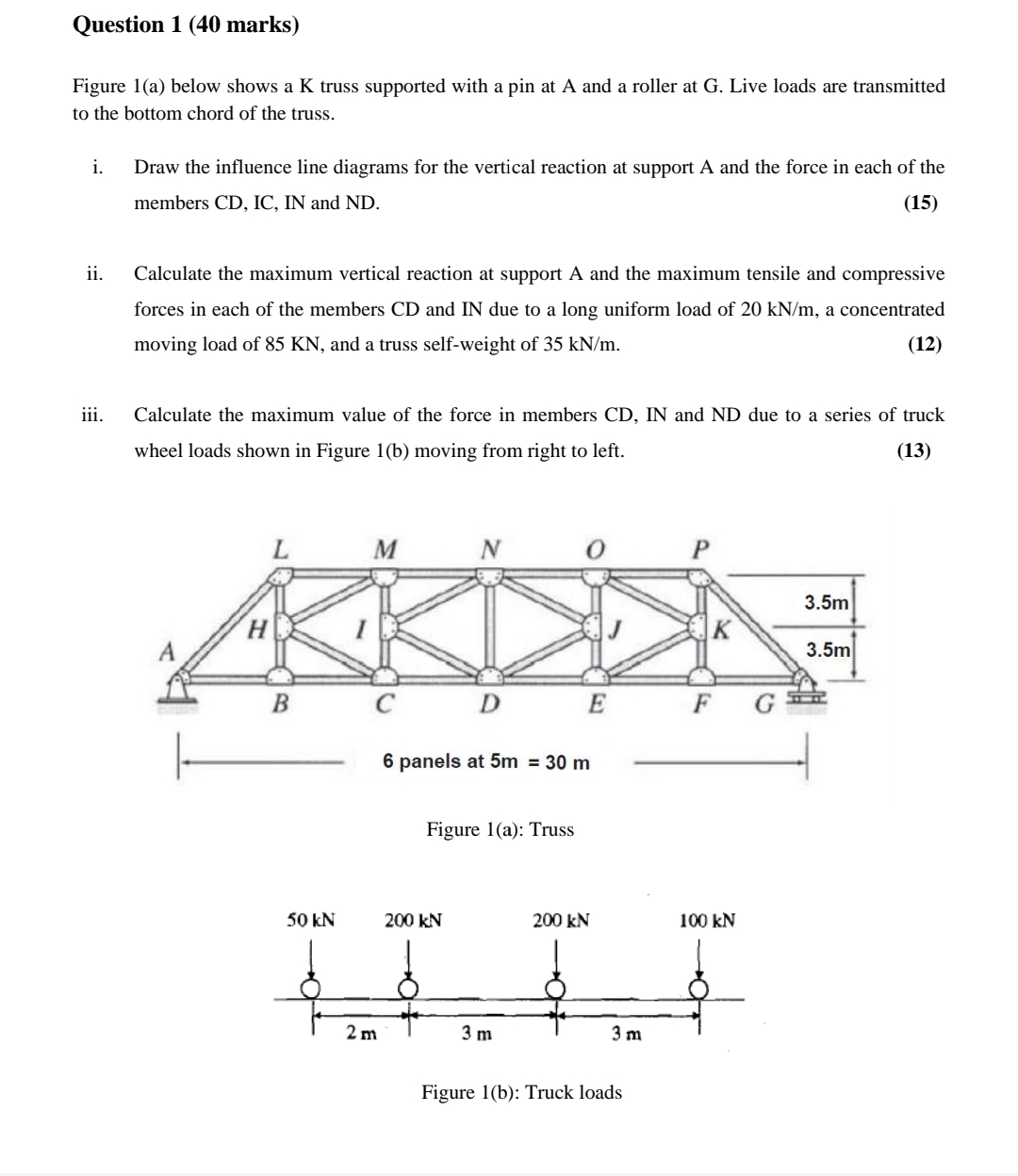
Figure a below shows a truss supported with a pin at A and a roller at G Live loads are transmitted to the bottom chord of the truss.
i Draw the influence line diagrams for the vertical reaction at support A and the force in each of the members CD IC IN and ND
ii Calculate the maximum vertical reaction at support A and the maximum tensile and compressive forces in each of the members CD and IN due to a long uniform load of a concentrated moving load of and a truss selfweight of
iii. Calculate the maximum value of the force in members and ND due to a series of truck wheel loads shown in Figure b moving from right to left.
Figure a: Truss
Step by Step Solution
There are 3 Steps involved in it
1 Expert Approved Answer
Step: 1 Unlock

Question Has Been Solved by an Expert!
Get step-by-step solutions from verified subject matter experts
Step: 2 Unlock
Step: 3 Unlock