

Question: Question 1 ( 4 0 marks ) The structure shown in the below figure is fixed at Node A and constrained with roller support at
Question
marks
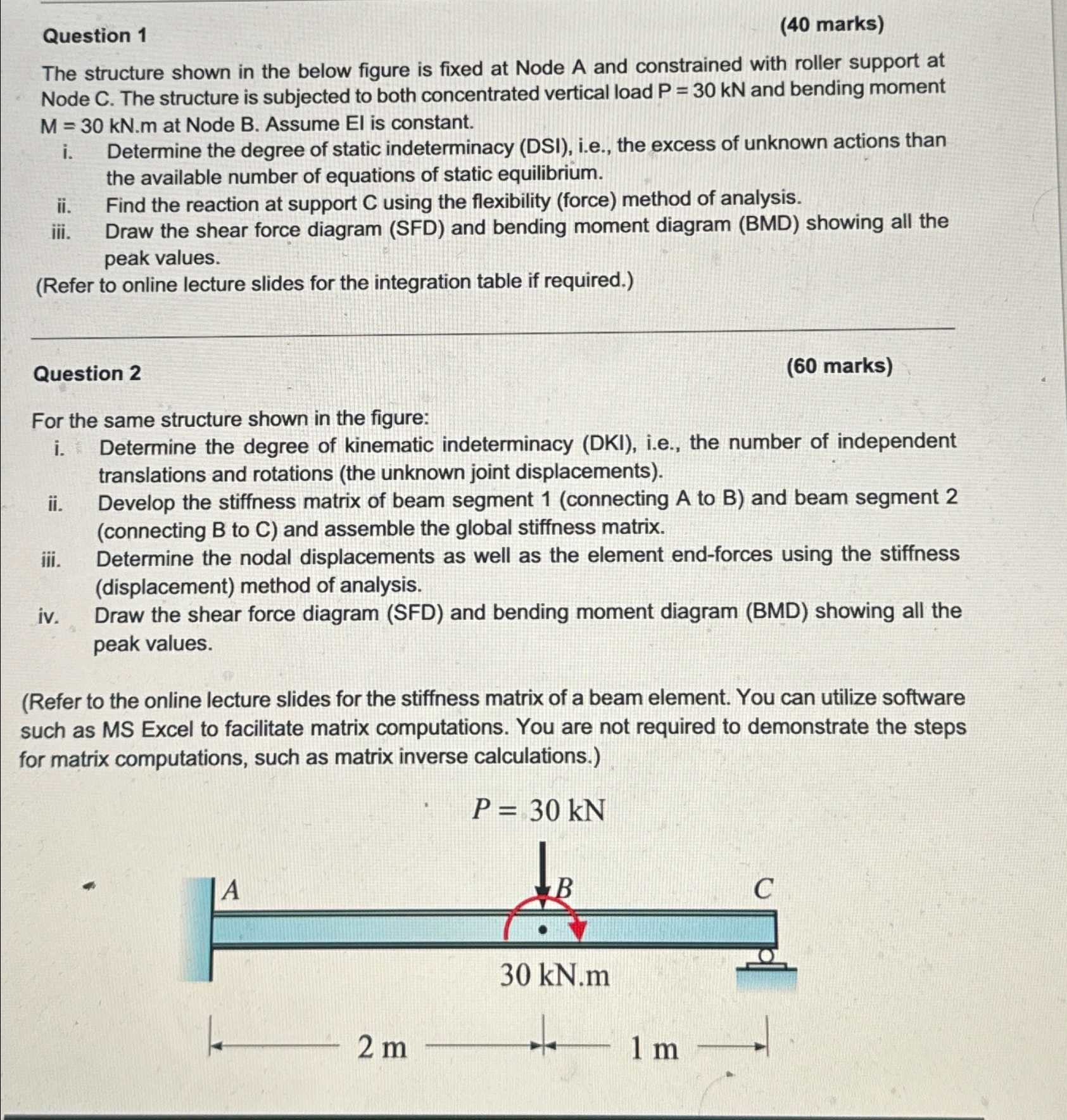
The structure shown in the below figure is fixed at Node A and constrained with roller support at Node The structure is subjected to both concentrated vertical load and bending moment at Node B Assume El is constant.
i Determine the degree of static indeterminacy DSI ie the excess of unknown actions than the available number of equations of static equilibrium.
ii Find the reaction at support using the flexibility force method of analysis.
iii. Draw the shear force diagram SFD and bending moment diagram BMD showing all the peak values.
Refer to online lecture slides for the integration table if required.
Question
marks
For the same structure shown in the figure:
i Determine the degree of kinematic indeterminacy DKI ie the number of independent translations and rotations the unknown joint displacements
ii Develop the stiffness matrix of beam segment connecting A to B and beam segment connecting to and assemble the global stiffness matrix.
iii. Determine the nodal displacements as well as the element endforces using the stiffness displacement method of analysis.
iv Draw the shear force diagram SFD and bending moment diagram BMD showing all the peak values.
Refer to the online lecture slides for the stiffness matrix of a beam element. You can utilize software such as MS Excel to facilitate matrix computations. You are not required to demonstrate the steps for matrix computations, such as matrix inverse calculations.
Step by Step Solution
There are 3 Steps involved in it
1 Expert Approved Answer
Step: 1 Unlock

Question Has Been Solved by an Expert!
Get step-by-step solutions from verified subject matter experts
Step: 2 Unlock
Step: 3 Unlock