

Question: Question 1 5 : Determine the maximum design bending moment, M d , caused by the UDL being placed in two contiguous bays for the
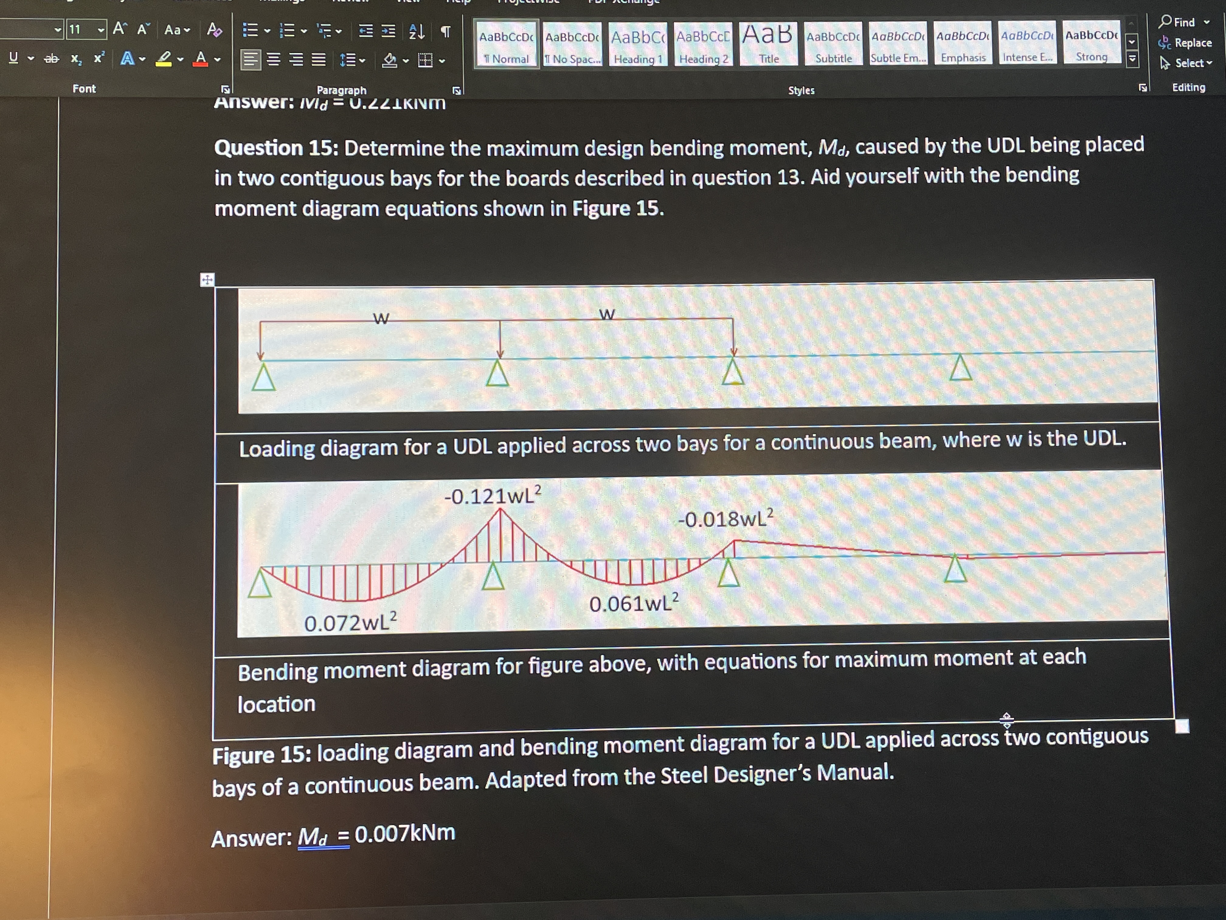
Question : Determine the maximum design bending moment, caused by the UDL being placed in two contiguous bays for the boards described in question Aid yourself with the bending moment diagram equations shown in Figure
Bending moment diagram for figure above, with equations for maximum moment at each location
Figure : loading diagram and bending moment diagram for a UDL applied across two contiguous bays of a continuous beam. Adapted from the Steel Designer's Manual.
Answer:
Step by Step Solution
There are 3 Steps involved in it
1 Expert Approved Answer
Step: 1 Unlock

Question Has Been Solved by an Expert!
Get step-by-step solutions from verified subject matter experts
Step: 2 Unlock
Step: 3 Unlock