

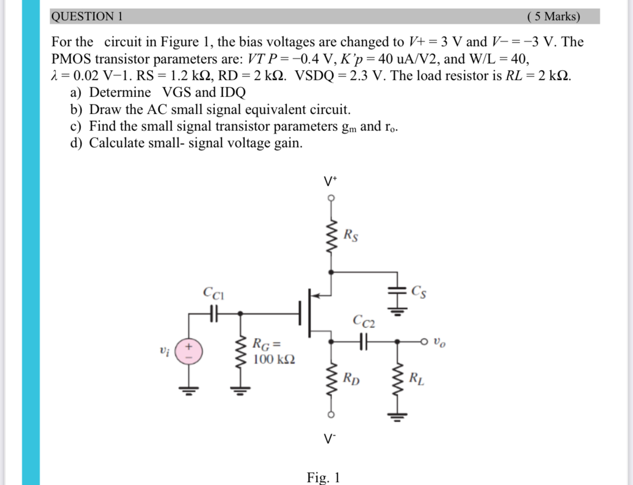
Question: QUESTION 1 ( 5 Marks ) For the circuit in Figure 1 , the bias voltages are changed to V + = 3 V and
QUESTION
Marks
For the circuit in Figure the bias voltages are changed to and The PMOS transistor parameters are: and The load resistor is
a Determine VGS and IDQ
b Draw the AC small signal equivalent circuit.
c Find the small signal transistor parameters and
d Calculate small signal voltage gain.
Fig.
Step by Step Solution
There are 3 Steps involved in it
1 Expert Approved Answer
Step: 1 Unlock

Question Has Been Solved by an Expert!
Get step-by-step solutions from verified subject matter experts
Step: 2 Unlock
Step: 3 Unlock