

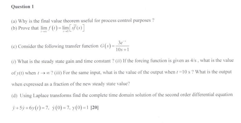
Question: Question 1 (a) Why is the final value theorem useful for process control purposes ? (b) Prove that lim f(1) = lim[$7(s)] 3e* 10s
![control purposes ? (b) Prove that lim f(1) = lim[$7(s)] 3e* 10s](https://dsd5zvtm8ll6.cloudfront.net/si.experts.images/questions/2022/07/62c57af32ec33_Screenshot632.png)

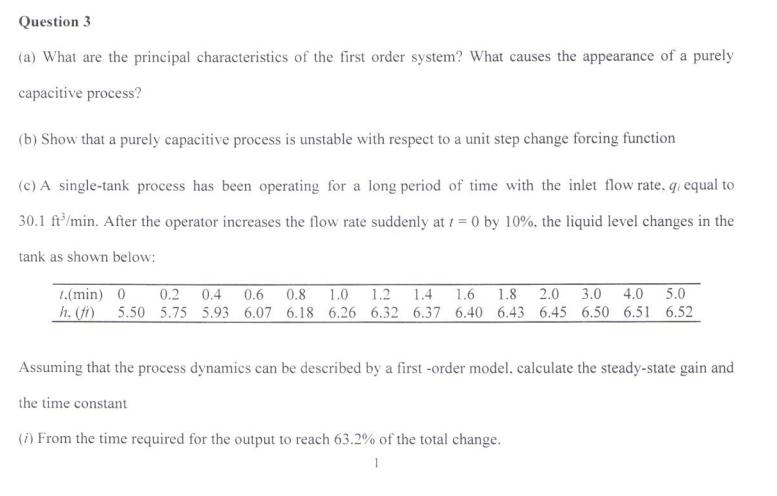

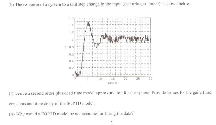
Question 1 (a) Why is the final value theorem useful for process control purposes ? (b) Prove that lim f(1) = lim[$7(s)] 3e* 10s +1 (i) What is the steady state gain and time constant ? (ii) If the forcing function is given as 4/s, what is the value of y(t) when ? (iii) For the same input, what is the value of the output when/=10 s? What is the output when expressed as a fraction of the new steady state value? (d) Using Laplace transforms find the complete time domain solution of the second order differential equation +5+6y()=7, y(0)=7, y(0)=1 [20] (c) Consider the following transfer function G(s)= Question 2 (a) Outline the steps one should take during the development of a mathematical model for chemical/metallurgical process control. (b) Consider the two systems shown below. System 1 differs from system 2 by the fact that the level of liquid in tank 2 does not affect the effluent flow rate from tank 1, which is the case for system 2. Tank I System I Tank 2 FLEL Tank I System 2 Tank 2 (i) Develop the mathematical model for each of the two systems. (ii) What are the state variables for each system, and what type of balance equations have you used? (iii) Which mathematical model is easier to solve, that for system 1 or that for system 2? Why? Assume that the flow rate of an effluent stream from tank 1 is proportional to the hydrostatic liquid pressure that causes the flow of liquid. The cross section are of tank 1 is 41 (f) and of tank 2 is A2 (fr) for both systems. The Flow rates F, F and F3 are in ft/min. [20] Question 3 (a) What are the principal characteristics of the first order system? What causes the appearance of a purely capacitive process? (b) Show that a purely capacitive process is unstable with respect to a unit step change forcing function (c) A single-tank process has been operating for a long period of time with the inlet flow rate. q, equal to 30.1 ft/min. After the operator increases the flow rate suddenly at t=0 by 10%. the liquid level changes in the tank as shown below: 1.(min) 0 0.2 0.4 0.6 0.8 1.0 1.2 1.4 1.6 1.8 2.0 3.0 4.0 5.0 5.50 5.75 5.93 6.07 6.18 6.26 6.32 6.37 6.40 6.43 6.45 6.50 6.51 6.52 Assuming that the process dynamics can be described by a first-order model, calculate the steady-state gain and the time constant (7) From the time required for the output to reach 63.2% of the total change. (ii) From the initial slope of the response curve. [20] Question 4 (a) With the aid of a well labeled diagram, describe the characteristics of an underdamped second order system. Your answer should be in reference to the sketch and it should include the appropriate equations. (b) The set point of the control system under proportional control (K-5) undergoes a step change of magnitude and assuming the transfer function of the measuring device is unity: 1 2. For G, (s)G, (s) = (s+1)(2s+1) (i) Determine the characteristic equation for the system (ii) Determine when the maximum value of y occurs (iii) Determine the offset (iv) Determine the period of oscillation (v) Sketch y(t) as a function of time showing key characteristics as determined in ii, iii and iv. [20] Question 5 (a) Compare and contrast the Cohen-Coon method with the Ziegler-Nichols method for tuning of feedback controllers (b) The response of a system to a unit step change in the input (occurring at time 0) is shown below. 1.6 1.4 1.2 1 y 0.8 0,6 0.4 0.2 10 20 25 15 Time (s) (i) Derive a second order plus dead time model approximation for the system. Provide values for the gain, time constants and time delay of the SOPTD model. (ii) Why would a FOPTD model be not accurate for fitting the data? 2 (iii) Select the controller settings for the Cohen-Coon method if a PI controller is used. Supposed a PID controller was used instead what significant differences in the tuning parameters would you expect to see? [20]
Step by Step Solution
3.34 Rating (160 Votes )
There are 3 Steps involved in it
a final value theorem is value of response b value with this theorem ie at t4 t... View full answer

Get step-by-step solutions from verified subject matter experts