

Question: Question 1 (Digital Circuits) Your task is to design a digital circuit which implements a version of a shift logical left oi a shift logical
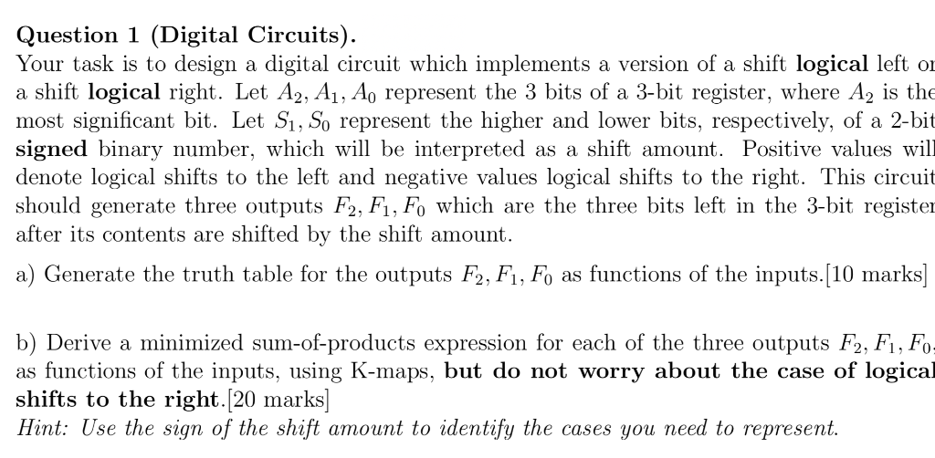
Question 1 (Digital Circuits) Your task is to design a digital circuit which implements a version of a shift logical left oi a shift logical right. Let A2, A1, Ao represent the 3 bits of a 3-bit register, where A2 is the most significant bit. Let Si, So represent the higher and lower bits, respectively, of a 2-bit signed binary number, which will be interpreted as a shift amount. Positive values will denote logical shifts to the left and negative values logical shifts to the right. This circuit should generate three outputs F2, F1, Fo which are the three bits left in the 3-bit registe after its contents are shifted by the shift amount. a) Generate the truth table for the outputs F2, F1, Fo as functions of the inputs.[10 marks b) Derive a minimized sum-of-products expression for each of the three outputs F2, Fi, Fo as functions of the inputs, using K-maps, but do not worry about the case of logical shifts to the right.[20 marks] Hint: Use the sign of the shift amount to identify the cases you need to represent
Step by Step Solution
There are 3 Steps involved in it

Get step-by-step solutions from verified subject matter experts