Question: Question 1 The frame supports the point load P at point C. The pins at A and B have diameters of 50 mm and 64
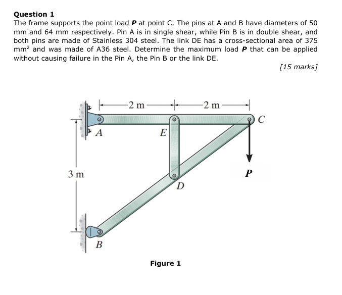
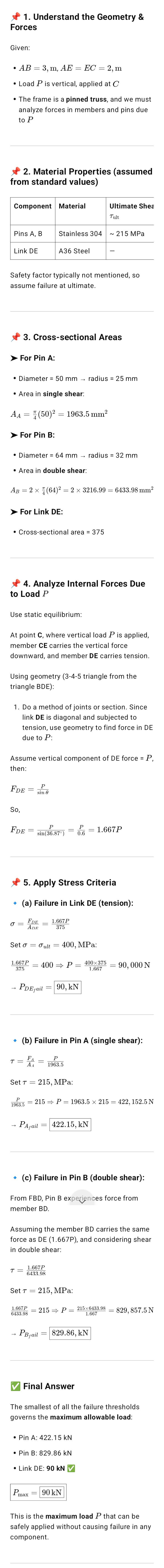
Question 1 The frame supports the point load P at point C. The pins at A and B have diameters of 50 mm and 64 mm respectively. Pin A is in single shear, while Pin B is in double shear, and both pins are made of Stainless 304 steel. The link DE has a cross-sectional area of 375 mm? and was made of A36 steel. Determine the maximum load P that can be applied without causing failure in the Pin A, the Pin B or the link DE. [15 marks] _ Figure 1 1. Understand the Geometry & Forces Given: . AB = 3, m, AE = EC = 2, m . Load P is vertical, applied at C . The frame is a pinned truss, and we must analyze forces in members and pins due to P 2. Material Properties (assumed from standard values) Component Material Ultimate Shea Tult Pins A, B Stainless 304 ~ 215 MPa Link DE A36 Steel Safety factor typically not mentioned, so assume failure at ultimate 3. Cross-sectional Areas For Pin A: . Diameter = 50 mm - radius = 25 mm . Area in single shear: AA = (50)2 = 1963.5 mm > For Pin B: . Diameter = 64 mm - radius = 32 mm . Area in double shear AB = 2 x (64)? = 2 x 3216.99 = 6433.98 mm > For Link DE: . Cross-sectional area = 375 4. Analyze Internal Forces Due to Load P Use static equilibrium: At point C, where vertical load P is applied, member CE carries the vertical force downward, and member DE carries tension. Using geometry (3-4-5 triangle from the triangle BDE): 1. Do a method of joints or section. Since link DE is diagonal and subjected to tension, use geometry to find force in DE due to P: Assume vertical component of DE force = P then; FDE = in So. FDE = Sin(36.87-) = 0.6 = 1.667P 5. Apply Stress Criteria . (a) Failure in Link DE (tension): 0 = DE = 975 Set o = Cult = 400, MPa: 1-667P = 400 = P = 400X375 = 90, 000 N PDEjail = 90, kN . (b) Failure in Pin A (single shear): T = = 1963.5 Set 7 = 215, MPa: 1963.5 = 215 = P = 1963.5 x 215 = 422, 152.5 N PAjail = 422.15, kN . (c) Failure in Pin B (double shear): From FBD, Pin B experiences force from member BD. Assuming the member BD carries the same force as DE (1.667P), and considering shear in double shear: T = 6434-98 Set 7 = 215, MPa: 6493 28 = 215 = P = 215x6453.98 = 829, 857.5 N - PBjail = 829.86, kN Final Answer The smallest of all the failure thresholds governs the maximum allowable load: . Pin A: 422.15 kN . Pin B: 829.86 KN . Link DE: 90 KN Pmax = 90 kN This is the maximum load P that can be safely applied without causing failure in any component.\\ Understanding the Structure The given frame is a truss-type structure consisting of several members and joints. A vertical load P is applied at point , and the force is transferred through the structure to the supports at A and B Three parts of the structure are at risk of, failure 1. Pin A, which is in single shear 2. Pin B, which is in double shear 3. Link DE, which is a member under tension We are to find the maximum load P that does not cause failure in any of these three parts \\. Geometry and Force Transfer The distances given in the diagram are + Horizontal: 2 m between A and E, 2m between E and C * Vertical: 3 m from A to B and also vertically from E to D This forms right-angled triangles in the structure, which helps to determine the direction and magnitude of internal forces. The vertical load P at point C causes internal forces in the members CE, DE, and BD, transferring the force through the frame to supports A and B. Sf Failure Criteria: What We're Checking We want to prevent: + Shear failure in Pins A and 8 + Tensile failure in Link DE Each failure mode has a stress limit * Stainless steel pins (A and 8) fail in shear around 215 MPa + A36 steel link (DE) fails in tension around 400 MPa , Step-by-Step Calculations 1. Force in Link DE due to Load P From geometry: + DE is a diagonal forming a triangle with a vertical side of 3 m and a horizontal side of 4m * This forms a 3-4-5,yiangle, so the length of DE= 5m The angle 9 of DE is: a Since link DE resists the vertical force P, the force in DE is larger than P because its diagonal. The vertical component of force in Deis Fog sind = P = For = ify = f= 1.067 2. Check for Tensile Failure in Link DE The tensile stress in link DE is: o = Fon = 1000 fon = ie Set this equal to the tensile strength of A36 steel (400 MPa): Noa = 90,000 = 90kN So, if P exceeds 90 kN, link DE will fall 3. Check for Shear Failure in Pin A (Single Shear) Pin A has a diameter of 50 mm, so its shear Aa = -(50)? = 1963.5 mm? The shear force in Pin A due to P is assumed equal to P (since it supports vertical force through member AE), Shear stress: T= joss Set it equal to the shear strength (21 MPa). fy = 205 + P= 10085-215: 12.5 = 420154 So, at 422.15 KN, which is much higher than 90 KN. 4, Check for Shear Failure in Pin B (Double Shear) Pin B has a diameter of 64 mm, and since It's in double shear, the effective area is: Ap 6433.98 mm? 5 -(64)? Pin B carries the same force as in link DE, which is 1.667P_ So: Set it equal to 215 MPa: Lag = 20s > P= 985 ~ 90,9575 = s0080N So, Pin B fails at 829.86 KN, also much higher than 90 kN. Final Conclusion 'Among all components: * Link DE fails at 90 kN + Pin A fails at 422.15 KN + Pin 8 fails at 829.86 KN Therefore, the weakest component is the link DE, and the structure fails when: P=90kN This is the maximum safe load that can be applied to point C without failure in any component
Step by Step Solution
There are 3 Steps involved in it
1 Expert Approved Answer
Step: 1 Unlock
Question Has Been Solved by an Expert!
Get step-by-step solutions from verified subject matter experts
Step: 2 Unlock
Step: 3 Unlock
Students Have Also Explored These Related Accounting Questions!