

Question: Question 1-5. 1-3 Consider a switch-mode de power supply represented by the circuit in Fig. 1-4a. The input dc voltage Va = 20 V and
Question 1-5.
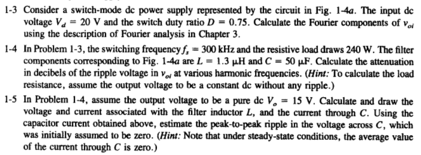
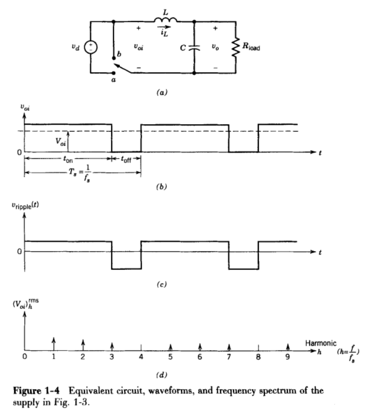
1-3 Consider a switch-mode de power supply represented by the circuit in Fig. 1-4a. The input dc voltage Va = 20 V and the switch duty ratio D = 0.75. Calculate the Fourier components of voi using the description of Fourier analysis in Chapter 3. 1-4 In Problem 1-3, the switching frequency f, = 300 kHz and the resistive load draws 240 W. The filter components corresponding to Fig. 1-4a are L = 1.3 uH and C = 50 uF. Calculate the attenuation in decibels of the ripple voltage in vojat various harmonic frequencies. (Hint: To calculate the load resistance, assume the output voltage to be a constant dc without any ripple.) 1-5 In Problem 1-4, assume the output voltage to be a pure dc V. 15 V. Calculate and draw the voltage and current associated with the filter inductor L, and the current through C. Using the capacitor current obtained above, estimate the peak-to-peak ripple in the voltage across C, which was initially assumed to be zero. (Hint: Note that under steady-state conditions, the average value of the current through C is zero.) ud Voi vo Rioad (a) Voi 0 ton t-toft 7.- (6) Uripplelt) (c) (Voith rms Harmonic (h=4 0 1 2 3 3 5 6 7 OD 9 (d) Figure 1-4 Equivalent circuit, waveforms, and frequency spectrum of the supply in Fig. 1-3. 1-3 Consider a switch-mode de power supply represented by the circuit in Fig. 1-4a. The input dc voltage Va = 20 V and the switch duty ratio D = 0.75. Calculate the Fourier components of voi using the description of Fourier analysis in Chapter 3. 1-4 In Problem 1-3, the switching frequency f, = 300 kHz and the resistive load draws 240 W. The filter components corresponding to Fig. 1-4a are L = 1.3 uH and C = 50 uF. Calculate the attenuation in decibels of the ripple voltage in vojat various harmonic frequencies. (Hint: To calculate the load resistance, assume the output voltage to be a constant dc without any ripple.) 1-5 In Problem 1-4, assume the output voltage to be a pure dc V. 15 V. Calculate and draw the voltage and current associated with the filter inductor L, and the current through C. Using the capacitor current obtained above, estimate the peak-to-peak ripple in the voltage across C, which was initially assumed to be zero. (Hint: Note that under steady-state conditions, the average value of the current through C is zero.) ud Voi vo Rioad (a) Voi 0 ton t-toft 7.- (6) Uripplelt) (c) (Voith rms Harmonic (h=4 0 1 2 3 3 5 6 7 OD 9 (d) Figure 1-4 Equivalent circuit, waveforms, and frequency spectrum of the supply in Fig. 1-3
Step by Step Solution
There are 3 Steps involved in it

Get step-by-step solutions from verified subject matter experts