

Question: Question 2 ( 1 0 points ) Water flows through the piping system shown above ( ( D = 2 0 0 mathrm
Question points
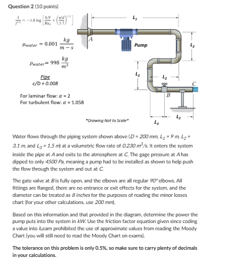
Water flows through the piping system shown above Dmathrm~mm Lmathrm~m L m and leftLmathrm~mright at a volumetric flow rate of mathrm~mmathrms It enters the system inside the pipe at A and exits to the atmosphere at C The gage pressure at A has dipped to only Pa meaning a pump had to be installed as shown to help push the flow through the system and out at C
The gate valve at B is fully open, and the elbows are all regular circ elbows. All fittings are flanged, there are no entrance or exit effects for the system, and the diameter can be treated as inches for the purposes of reading the minor losses chart for your other calculations, use mm
Based on this information and that provided in the diagram, determine the power the pump puts into the system in k W Use the friction factor equation given since coding a value into ilearn prohibited the use of approximate values from reading the Moody Chart you will still need to read the Moody Chart on exams
The tolerance on this problem is only so make sure to carry plenty of decimals in your calculations.
Step by Step Solution
There are 3 Steps involved in it
1 Expert Approved Answer
Step: 1 Unlock

Question Has Been Solved by an Expert!
Get step-by-step solutions from verified subject matter experts
Step: 2 Unlock
Step: 3 Unlock