

Question: Question 2 ( 2 0 Marks ) As illustrated in Fig. 2 , the high - frequency full - wave quasi - resonant buck converter
Question Marks
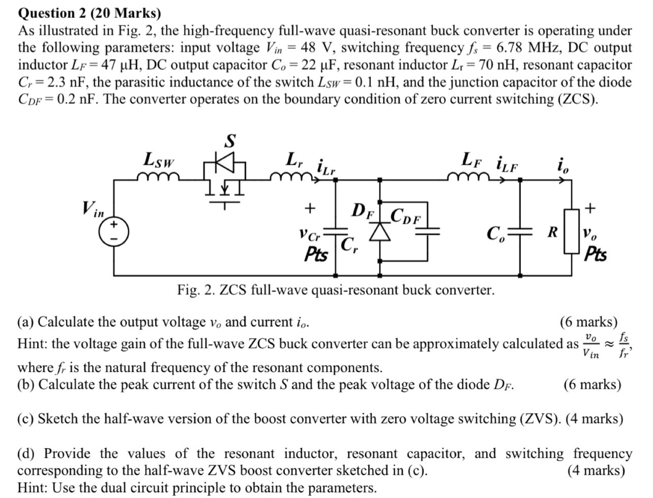
As illustrated in Fig. the highfrequency fullwave quasiresonant buck converter is operating under the following parameters: input voltage switching frequency output inductor DC output capacitor resonant inductor resonant capacitor the parasitic inductance of the switch and the junction capacitor of the diode The converter operates on the boundary condition of zero current switching ZCS
a Calculate the output voltage and current
marks
Hint: the voltage gain of the fullwave ZCS buck converter can be approximately calculated as ~~ where is the natural frequency of the resonant components.
b Calculate the peak current of the switch and the peak voltage of the diode
marks
c Sketch the halfwave version of the boost converter with zero voltage switching ZVS marks
d Provide the values of the resonant inductor, resonant capacitor, and switching frequency corresponding to the halfwave ZVS boost converter sketched in c
marks Hint: Use the dual circuit principle to obtain the parameters.
Step by Step Solution
There are 3 Steps involved in it
1 Expert Approved Answer
Step: 1 Unlock

Question Has Been Solved by an Expert!
Get step-by-step solutions from verified subject matter experts
Step: 2 Unlock
Step: 3 Unlock