

Question: Question 2 : ( 3 0 pts The system described in the figure consists of a solid copper pipe A B ( 6 0 0
Question : pts
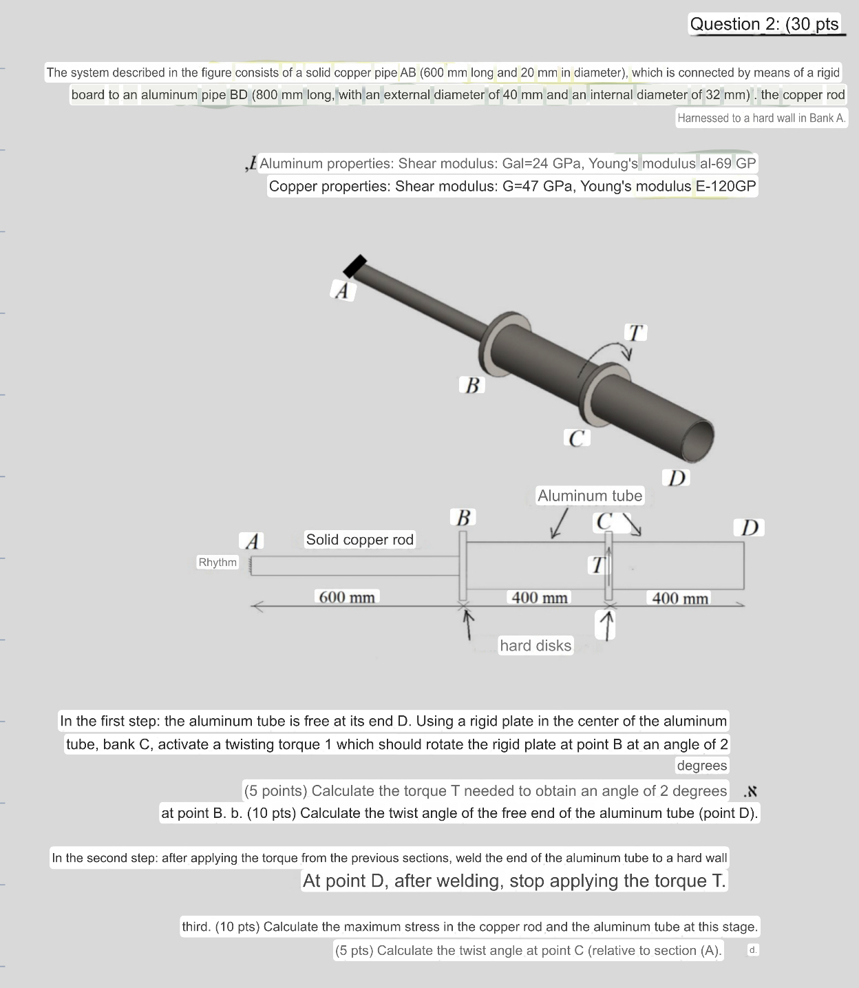
The system described in the figure consists of a solid copper pipe mm long and mm in diameter which is connected by means of a rigid board to an aluminum pipe mm long, with an external diameter of mm and an internal diameter of mm the copper rod
Harnessed to a hard wall in Bank A
L Aluminum properties: Shear modulus: Gal GPa, Young's modulus al GP Copper properties: Shear modulus: G GPa, Young's modulus EGP
In the first step: the aluminum tube is free at its end D Using a rigid plate in the center of the aluminum tube, bank activate a twisting torque which should rotate the rigid plate at point at an angle of
degrees
points Calculate the torque T needed to obtain an angle of degrees at point B b pts Calculate the twist angle of the free end of the aluminum tube point D
In the second step: after applying the torque from the previous sections, weld the end of the aluminum tube to a hard wall At point D after welding, stop applying the torque
third. pts Calculate the maximum stress in the copper rod and the aluminum tube at this stage.
pts Calculate the twist angle at point relative to section A
Step by Step Solution
There are 3 Steps involved in it
1 Expert Approved Answer
Step: 1 Unlock

Question Has Been Solved by an Expert!
Get step-by-step solutions from verified subject matter experts
Step: 2 Unlock
Step: 3 Unlock