

Question: QUESTION 2 (5 marks) Consider the following RLC circuit as shown in Figure 2, where u(t) is the current source and input of the
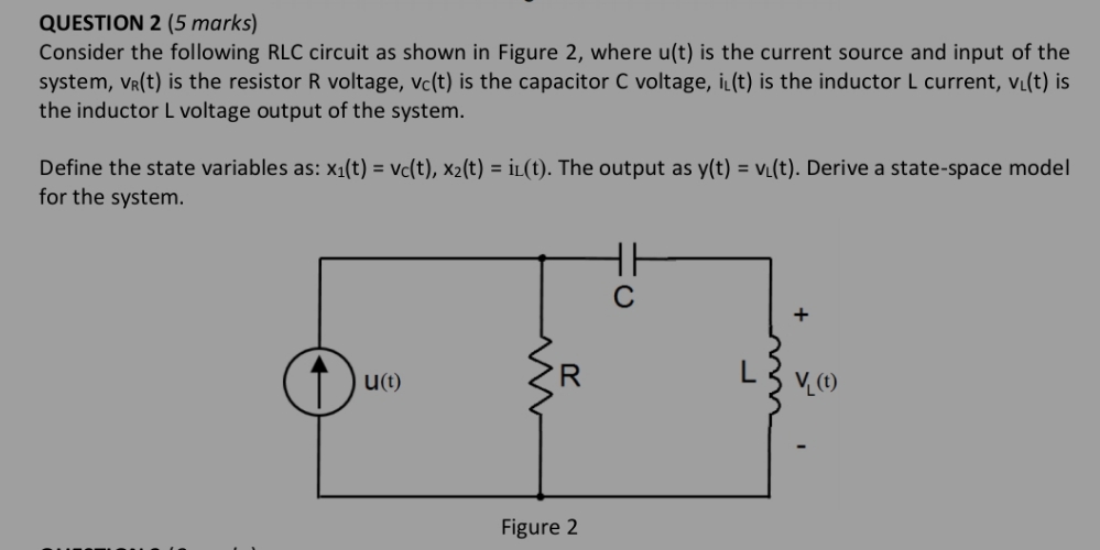
QUESTION 2 (5 marks) Consider the following RLC circuit as shown in Figure 2, where u(t) is the current source and input of the system, VR(t) is the resistor R voltage, vc(t) is the capacitor C voltage, i(t) is the inductor L current, vi(t) is the inductor L voltage output of the system. Define the state variables as: x1(t) = vc(t), x2(t) = iL(t). The output as y(t) = v(t). Derive a state-space model for the system. u(t) R w Figure 2 + V(t)
Step by Step Solution
There are 3 Steps involved in it
1 Expert Approved Answer
Step: 1 Unlock

Question Has Been Solved by an Expert!
Get step-by-step solutions from verified subject matter experts
Step: 2 Unlock
Step: 3 Unlock