

Question: Question 2: a) A spherical pressure vessel with a diameter of 700mm operates at a pressure of 8 MPa. The maximum allowable tensile stress
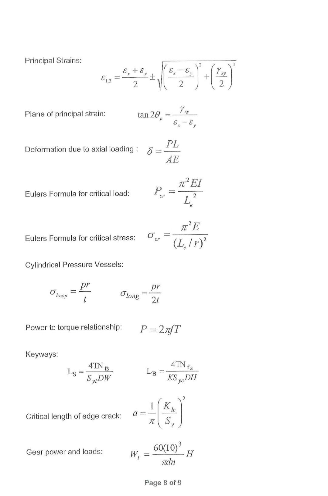
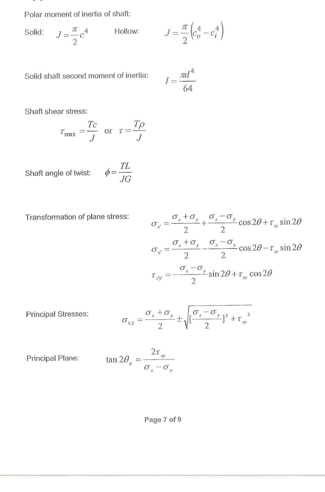
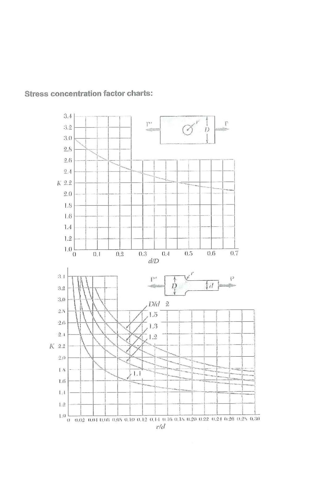
Question 2: a) A spherical pressure vessel with a diameter of 700mm operates at a pressure of 8 MPa. The maximum allowable tensile stress in the vessel is 150 MPa. Calculate the required thickness of the vessel. b) The torque generated on a solid steel shaft is 180Nm. Determine the minimum required diameter of the solid shaft if the maximum allowable shear stress of the steel is 100 MPa. Page 2 of 9 c) A force of 20 kN is applied to the member at point C, as shown in Figure 2(c). Calculate the normal stress in the supporting rod, which has a diameter of 25 mm. Rod diameter = 25mm C A B 3.5 m 1 m 20 kN Figure 2(c) d) An AISI-1020 member with a square cross section is to be used to safely support a tensile load of 500 kN. Use a safety factor of 2.5 to determine the dimensions of the cross section. Refer also to Table 2(d). Materials Steel Specific Yield Ultimate Modulus weight strength strength of elasticity (MPa) (kN/m) (MPa)a (GPa) Shear modulus Paisson's (GPa) radio AISI 1120, Cold-rulled 77 427 621 207 80 0.29 Principal Strains: 1,2 E-E 2 (55) (4) 2 Yxy Plane of principal strain: tan 20, = PL Deformation due to axial loading: 8 - Eulers Formula for critical load: Eulers Formula for critical stress: Cylindrical Pressure Vessels: P.... cr O cr AE 2 L (Le/r) pr pr hoop Olong 2t Power to torque relationship: P=27fT Keyways: 4TN fs 4TN fs LB === Ls - SDW KS yeDH Critical length of edge crack: a=- K Ic S y 2 Gear power and loads: 60(10) 3. W = H Tdn Page 8 of 9 Polar moment of inertia of shaft: Solid: J==c Hollow: J = (-4) 2 Solid shaft second moment of inertia: Shaft shear stress: Tmax Tc or T= J Shaft angle of twist: TL JG Transformation of plane stress: Principal Stresses: Principal Plane: tan 20, I Td4 64 Txy x y 2 + + 2 2 x X 2 2 y y cos 20+ Tsin 20 -T sin 20 cos 20-T sin 20+x cos 20 -0 y xy 2 2T xy y Page 7 of 9 2 Stress concentration factor charts: 3.4 3.2 3.0 2.8 2.6 2.4 K 2.2 2.0 1.S 1.6 1.4 1.2 1.0 () 0.1 (0,2 0.3 0.4 0.5 0.6 ().7 d/D 3.1 p d 3.2 3.4 Did 2 2.8 1.5 2.6 .1.3 24 1.2 K 2.2 2.0 IS 1.1 1.6 LA 1.2 1.0 Ch 1.02 0.04 0.06 0.45 0.10 0.12 0.14 0.16 0.15 0.20 0.22 0.21 0.26 0.25 0.30 rid
Step by Step Solution
There are 3 Steps involved in it

Get step-by-step solutions from verified subject matter experts