

Question: QUESTION 2 Figure 2 below shows a frame which is fixed at supports A and E , pinned at F , and supported by pin
QUESTION
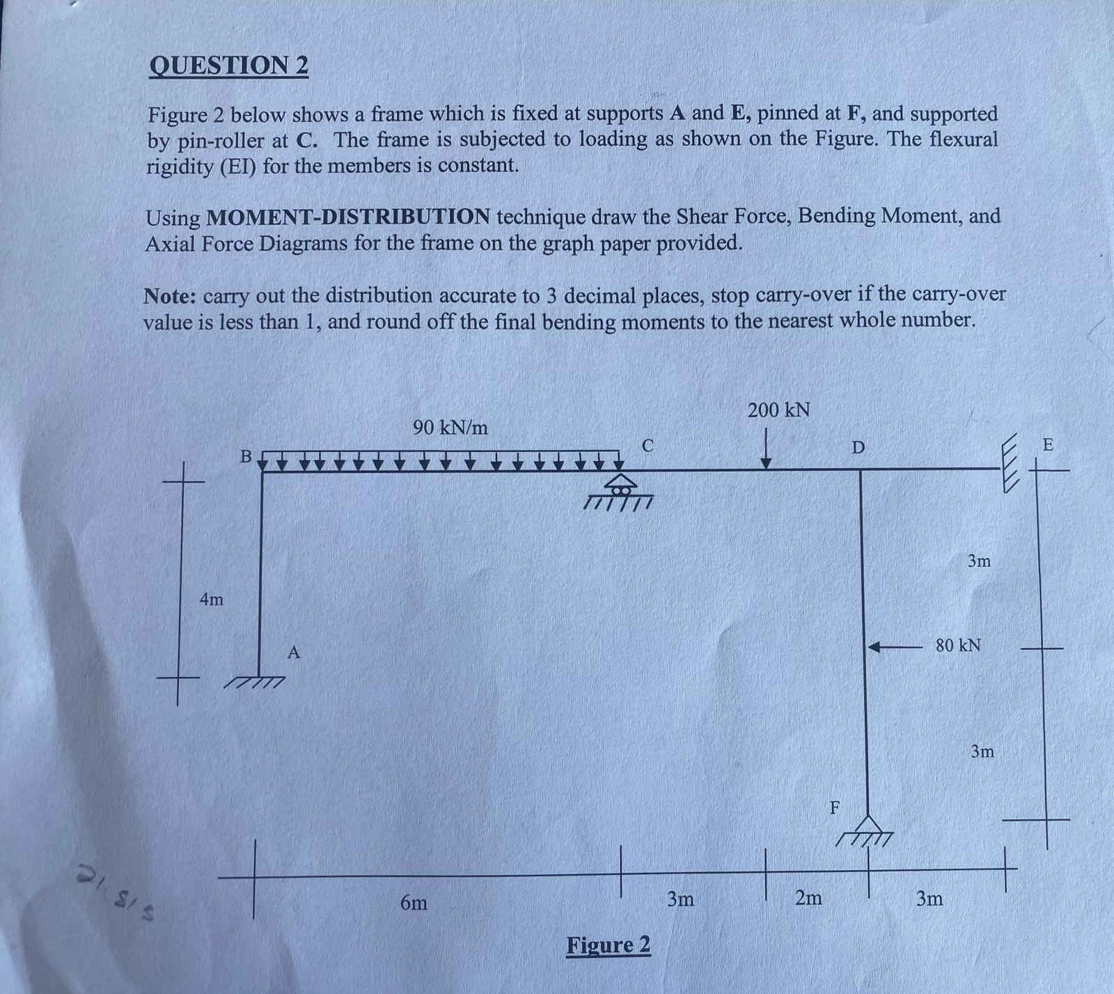
Figure below shows a frame which is fixed at supports A and pinned at and supported by pinroller at The frame is subjected to loading as shown on the Figure. The flexural rigidity EI for the members is constant.
Using MOMENTDISTRIBUTION technique draw the Shear Force, Bending Moment, and Axial Force Diagrams for the frame on the graph paper provided.
Note: carry out the distribution accurate to decimal places, stop carryover if the carryover value is less than and round off the final bending moments to the nearest whole number.
Figure
Step by Step Solution
There are 3 Steps involved in it
1 Expert Approved Answer
Step: 1 Unlock

Question Has Been Solved by an Expert!
Get step-by-step solutions from verified subject matter experts
Step: 2 Unlock
Step: 3 Unlock