

Question: Question 2 : For the plane ( 2 D ) frame shown below, evaluate transformation matrix [ T ] and nodal load vector in the
Question : For the plane D frame shown below, evaluate transformation matrix T and nodal
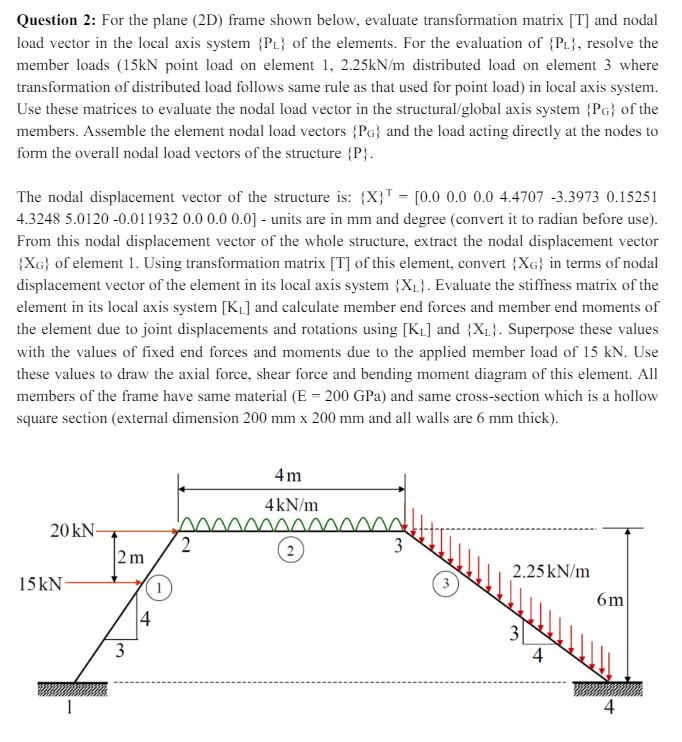
load vector in the local axis system of the elements. For the evaluation of resolve the
member loads point load on element distributed load on element where
transformation of distributed load follows same rule as that used for point load in local axis system.
Use these matrices to evaluate the nodal load vector in the structuralglobal axis system of the
members. Assemble the element nodal load vectors and the load acting directly at the nodes to
form the overall nodal load vectors of the structure
The nodal displacement vector of the structure is:
units are in and degree convert it to radian before use
From this nodal displacement vector of the whole structure, extract the nodal displacement vector
of element Using transformation matrix of this element, convert in terms of nodal
displacement vector of the element in its local axis system Evaluate the stiffness matrix of the
element in its local axis system and calculate member end forces and member end moments of
the element due to joint displacements and rotations using and Superpose these values
with the values of fixed end forces and moments due to the applied member load of Use
these values to draw the axial force, shear force and bending moment diagram of this element. All
members of the frame have same material GPa and same crosssection which is a hollow
square section external dimension and all walls are thickQuestion : For the plane D frame shown below, evaluate transformation matrix T and nodal
load vector in the local axis system of the elements. For the evaluation of resolve the
member loads point load on element distributed load on element where
transformation of distributed load follows same rule as that used for point load in local axis system.
Use these matrices to evaluate the nodal load vector in the structuralglobal axis system of the
members. Assemble the element nodal load vectors and the load acting directly at the nodes to
form the overall nodal load vectors of the structure
The nodal displacement vector of the structure is:
units are in and degree convert it to radian before use
From this nodal displacement vector of the whole structure, extract the nodal displacement vector
of element Using transformation matrix of this element, convert in terms of nodal
displacement vector of the element in its local axis system Evaluate the stiffness matrix of the
element in its local axis system and calculate member end forces and member end moments of
the element due to joint displacements and rotations using and Superpose these values
with the values of fixed end forces and moments due to the applied member load of Use
these values to draw the axial force, shear force and bending moment diagram of this element. All
members of the frame have same material GPa and same crosssection which is a hollow
square section external dimension and all walls are thick
Step by Step Solution
There are 3 Steps involved in it
1 Expert Approved Answer
Step: 1 Unlock

Question Has Been Solved by an Expert!
Get step-by-step solutions from verified subject matter experts
Step: 2 Unlock
Step: 3 Unlock