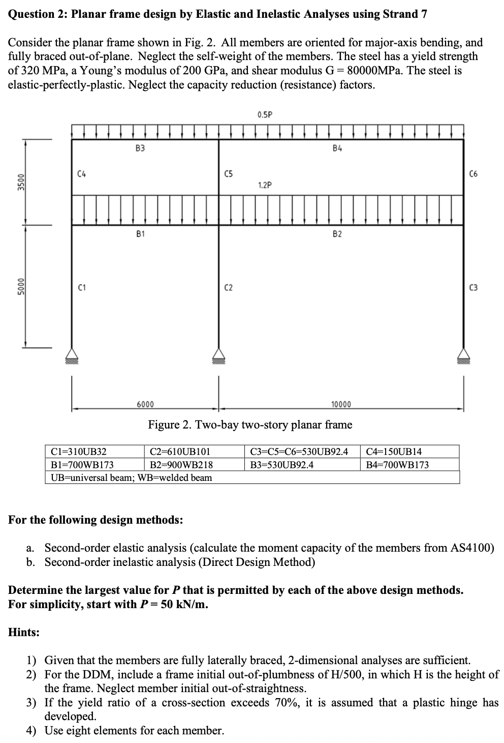
Question: Question 2: Planar frame design by Elastic and Inelastic Analyses using Strand 7 Consider the planar frame shown in Fig. 2. All members are oriented

Question 2: Planar frame design by Elastic andQuestion 2: Planar frame design by Elastic and
Question 2: Planar frame design by Elastic and Inelastic Analyses using Strand 7 Consider the planar frame shown in Fig. 2. All members are oriented for major-axis bending, and fully braced out-of-plane. Neglect the self-weight of the members. The steel has a yield strength of 320 MPa, a Young's modulus of 200 GPa, and shear modulus G = 80000MPa. The steel is elastic-perfectly-plastic. Neglect the capacity reduction (resistance) factors. 0.5P B3 B4 C4 C5 C6 3500 1.2P B1 BZ 5000 C1 C2 C3 6000 10000 Figure 2. Two-bay two-story planar frame C1=310UB32 C2=610UB101 C3=C5=C6=530UB92.4 C4=150UB14 B1=700WB173 B2=900WB218 B3=530UB92.4 B4=700WB173 UB=universal beam; WB=welded beam For the following design methods: a. Second-order elastic analysis (calculate the moment capacity of the members from AS4100) b. Second-order inelastic analysis (Direct Design Method) Determine the largest value for P that is permitted by each of the above design methods. For simplicity, start with P = 50 kN/m. Hints: 1) Given that the members are fully laterally braced, 2-dimensional analyses are sufficient. 2) For the DDM, include a frame initial out-of-plumbness of H/500, in which H is the height of the frame. Neglect member initial out-of-straightness. 3) If the yield ratio of a cross-section exceeds 70%, it is assumed that a plastic hinge has developed. 4) Use eight elements for each member.Questions 1) 2) 3) 4) 5) 6) When modelling the initial frame out-of-plumbness, the columns can lean to the left, or to the right. Which direction will you use? Justify your answer. Give calculation details, show how the largest value of P for the second-order elastic analysis is determined. Which member is the critical member? For the DDM, plot the load versus displacement response, in which the displacement = horizontal roof displacement at the left roof corner. At the largest value of P determined by DDM, show the locations of the plastic hinge(s) that have developed. Explain the plastic hinge sequence. What is the failure mode of the frame? What level of additional load capacity was realized by employing the DDM as compared to the elastic method? In your opinion, is this significant and worth the additional effort of completing an inelastic analysis? Engineers have often stated that the design of compact fully laterally braced frames by elastic analysis can be defined as a process of designing for the first plastic hinge. Based on the results of this study, do you agree or disagree? Justify your response

Step by Step Solution

There are 3 Steps involved in it

1 Expert Approved Answer
Step: 1 Unlock blur-text-image
Question Has Been Solved by an Expert!

Get step-by-step solutions from verified subject matter experts

Step: 2 Unlock
Step: 3 Unlock

Students Have Also Explored These Related Accounting Questions!