

Question: QUESTION 2 The loaded truss system shown in Figure Q 2 is pin - supported at joint A and supported on a roller at joint
QUESTION
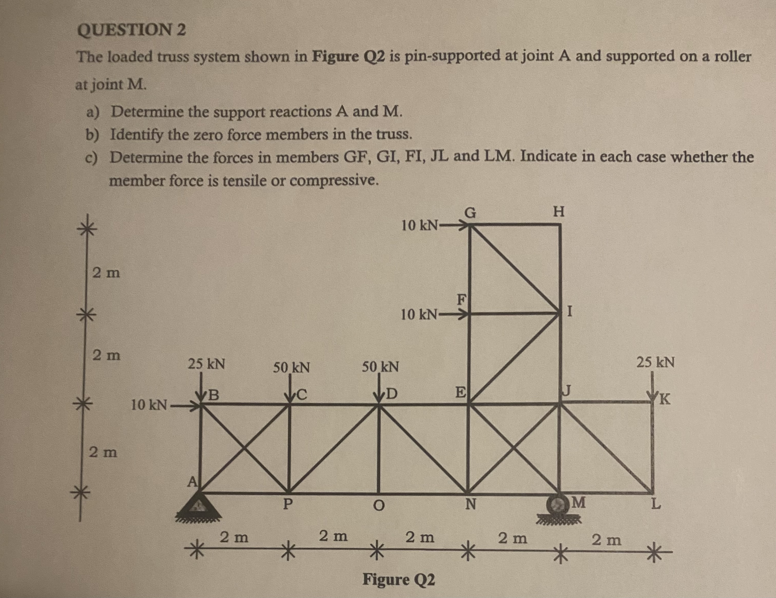
The loaded truss system shown in Figure is pinsupported at joint A and supported on a roller
at joint M
a Determine the support reactions A and
b Identify the zero force members in the truss.
c Determine the forces in members GF GI FI JL and LM Indicate in each case whether the
member force is tensile or compressive.
Step by Step Solution
There are 3 Steps involved in it
1 Expert Approved Answer
Step: 1 Unlock

Question Has Been Solved by an Expert!
Get step-by-step solutions from verified subject matter experts
Step: 2 Unlock
Step: 3 Unlock