

Question: Question 2 The pipe network shown in Figure 2 . 1 has the following data: All pipes are equal in length ( 1 0 0
Question
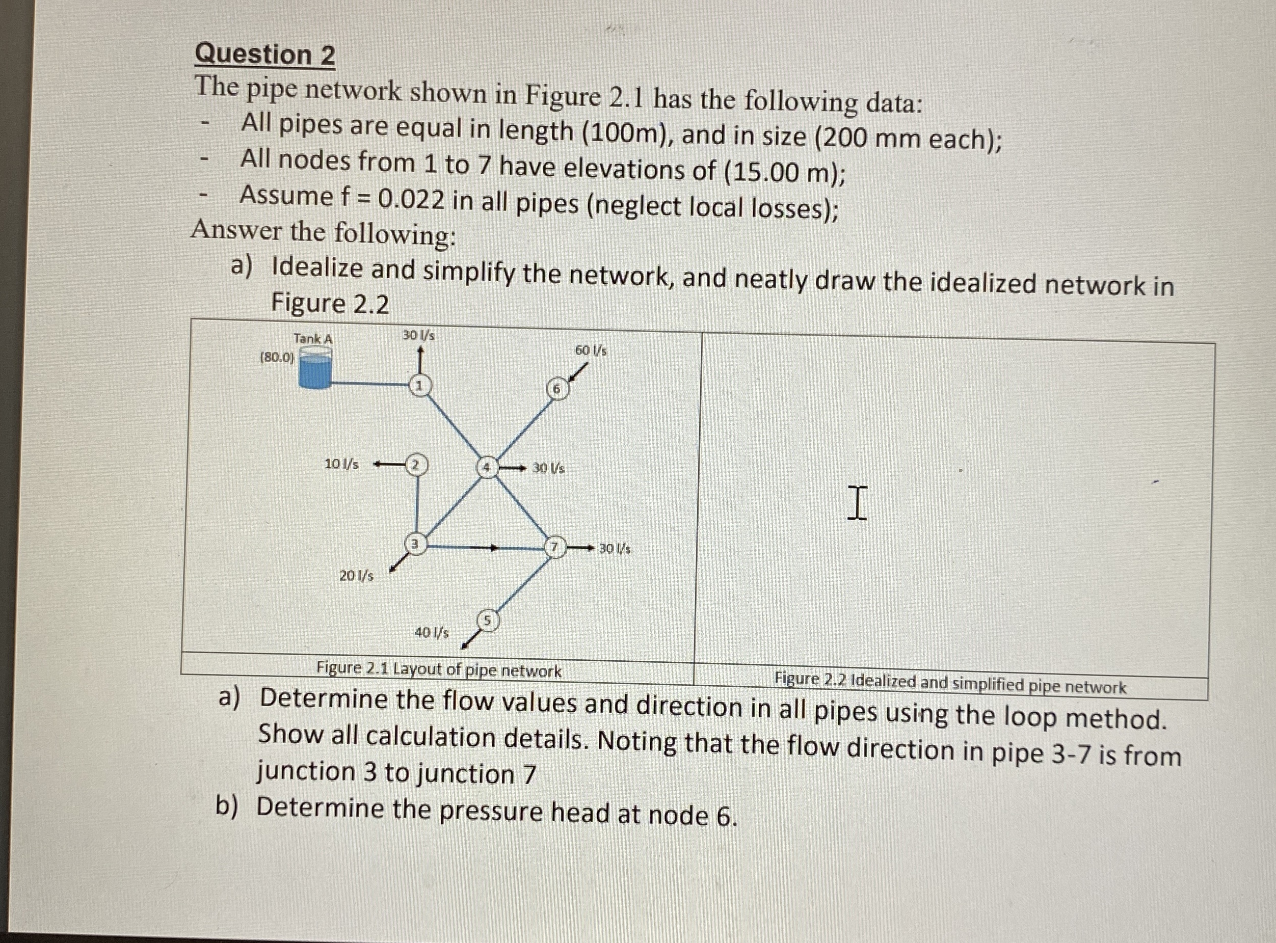
The pipe network shown in Figure has the following data:
All pipes are equal in length m and in size mm each;
All nodes from to have elevations of ;
Assume in all pipes neglect local losses;
Answer the following:
a Idealize and simplify the network, and neatly draw the idealized network in Figure
a Determine the flow values and direction in all pipes using the loop method. Show all calculation details. Noting that the flow direction in pipe is from junction to junction
b Determine the pressure head at node
Step by Step Solution
There are 3 Steps involved in it
1 Expert Approved Answer
Step: 1 Unlock

Question Has Been Solved by an Expert!
Get step-by-step solutions from verified subject matter experts
Step: 2 Unlock
Step: 3 Unlock