

Question: Question 2 The singly symmetric column shown in Fig. 2 a is loaded by a concentric compression force ( P ) . The crosssection dimensions
Question
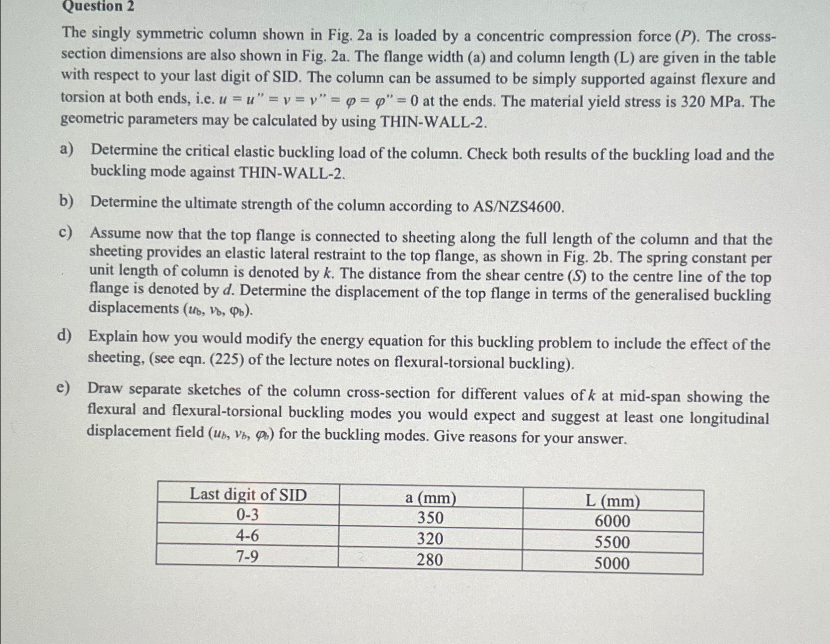
The singly symmetric column shown in Fig. is loaded by a concentric compression force The crosssection dimensions are also shown in Fig. a The flange width a and column length L are given in the table with respect to your last digit of SID. The column can be assumed to be simply supported against flexure and torsion at both ends, ie at the ends. The material yield stress is MPa. The geometric parameters may be calculated by using THINWALL
a Determine the critical elastic buckling load of the column. Check both results of the buckling load and the buckling mode against THINWALL
b Determine the ultimate strength of the column according to ASNZS
c Assume now that the top flange is connected to sheeting along the full length of the column and that the sheeting provides an elastic lateral restraint to the top flange, as shown in Fig. b The spring constant per unit length of column is denoted by The distance from the shear centre to the centre line of the top flange is denoted by Determine the displacement of the top flange in terms of the generalised buckling displacements
d Explain how you would modify the energy equation for this buckling problem to include the effect of the sheeting, see eqn. of the lecture notes on flexuraltorsional buckling
e Draw separate sketches of the column crosssection for different values of at midspan showing the flexural and flexuraltorsional buckling modes you would expect and suggest at least one longitudinal displacement field for the buckling modes. Give reasons for your answer.
tableLast digit of SID,
Step by Step Solution
There are 3 Steps involved in it
1 Expert Approved Answer
Step: 1 Unlock

Question Has Been Solved by an Expert!
Get step-by-step solutions from verified subject matter experts
Step: 2 Unlock
Step: 3 Unlock