

Question: Question 2F (20 marks) Show all calculations to 3 decimal places Show all interpolation Condenser #2 C Diagram 2 shows an ideal cascade vapour-compression heat
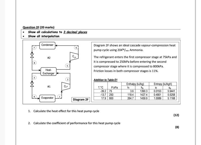
Question 2F (20 marks) Show all calculations to 3 decimal places Show all interpolation Condenser #2 C Diagram 2 shows an ideal cascade vapour-compression heat pump cycle using 204"/m Ammonia. The refrigerant enters the first compressor stage at 75kPa and it is compressed to 250kPa before entering the second compressor stage where it is compressed to 800kPa. Friction losses in both compressor stages is 11% 5 Heat- Exchanger 2 Addition to Table E1 #1 CUP T'C kPa -39.2 75 - 13.7 250 17.9 800 Enthalpy (kJ/kg) hi he 3.6 1390.3 118.4 1427 4 264.7 1459.9 Entropy (kJ/kg) SI Sg 0.0153 5.9441 0.4801 5.5258 1.0089 5.1168 Evaporator Diagram 2F 1. Calculate the heat effect for this heat pump cycle (12) 2. Calculate the coefficient of performance for this heat pump cycle (8)
Step by Step Solution
There are 3 Steps involved in it

Get step-by-step solutions from verified subject matter experts