

Question: Question 3 ( 1 0 marks ) Below is a circuit diagram of a temperature sensor based on a LM 3 9 3 operational amplifier
Question marks
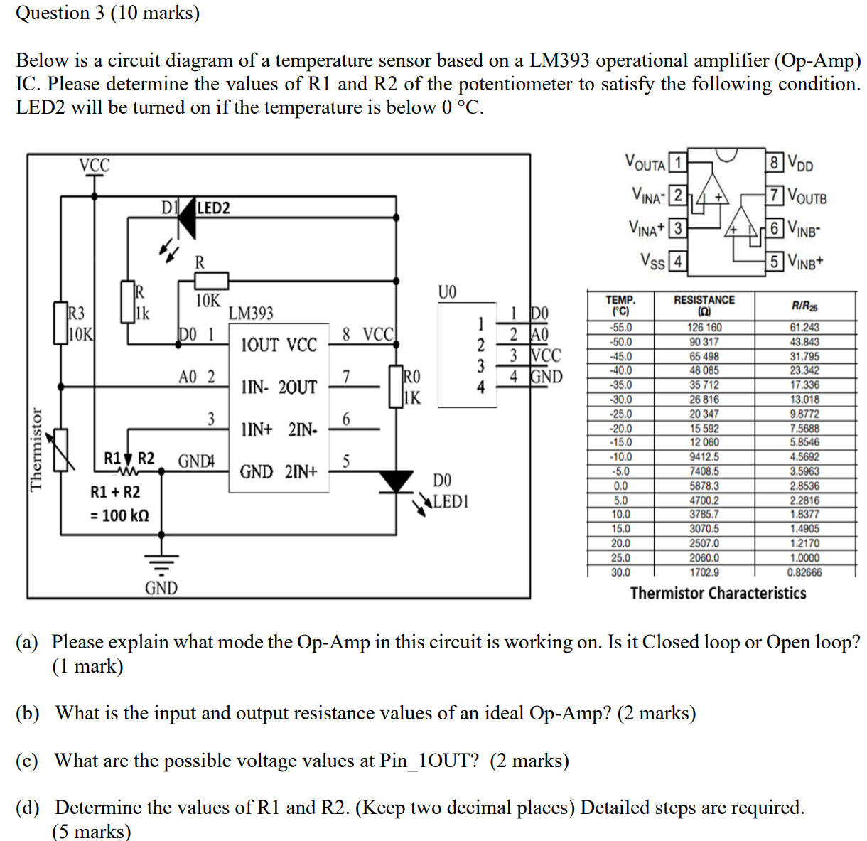
Below is a circuit diagram of a temperature sensor based on a LM operational amplifier OpAmp IC Please determine the values of R and R of the potentiometer to satisfy the following condition. LED will be turned on if the temperature is below circmathrmC
a Please explain what mode the OpAmp in this circuit is working on Is it Closed loop or Open loop? mark
b What is the input and output resistance values of an ideal OpAmp? marks
c What are the possible voltage values at PinOUT? marks
d Determine the values of R and RKeep two decimal places Detailed steps are required. marks
Step by Step Solution
There are 3 Steps involved in it
1 Expert Approved Answer
Step: 1 Unlock

Question Has Been Solved by an Expert!
Get step-by-step solutions from verified subject matter experts
Step: 2 Unlock
Step: 3 Unlock