

Question: QUESTION 3 115 marks] (a) Figure 3(a) shows a LAN and the MAC address table of the switch. Briefly explain what the switch does for
![QUESTION 3 115 marks] (a) Figure 3(a) shows a LAN and](https://s3.amazonaws.com/si.experts.images/answers/2024/09/66dd40ad0b55a_04466dd40ac8a451.jpg)
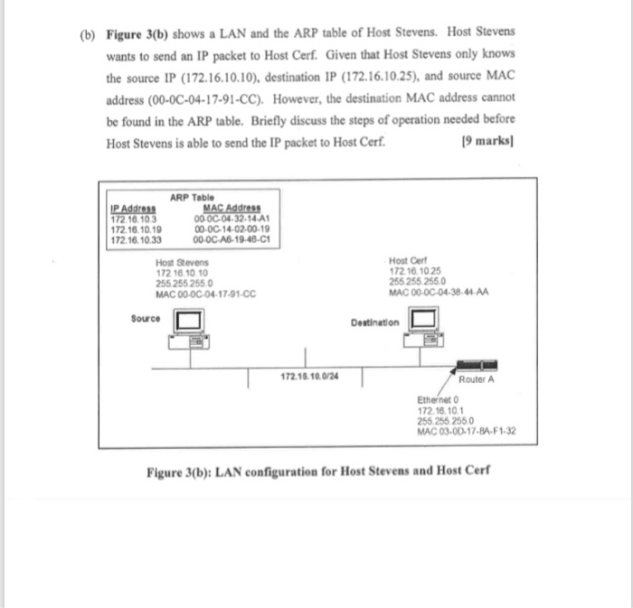
QUESTION 3 115 marks] (a) Figure 3(a) shows a LAN and the MAC address table of the switch. Briefly explain what the switch does for the following scenario: i) The switch receives a frame at port I with the source address 11-11-11 11-11-11 and the destination address 33-33-33-33-33-33.2 marks (ii) The switch receives a frame at port 1 with the source address 1 1-1 1-11. 1-11-11 and the destination address FF-FF-FF-FF-FF-FF. 2 marks ii) Both computers at port 1 and port 9 are sending a frame to destination 2 marks address 33-33-33-33-33-33 at the same time switc 33-3-3-33-33-33-33 22-22-22-22-22-22 44-44-44-44-44-44 MAC Address Table Part Source MAC.Add Part Source MAC Add 11-11-11-11-11-11 6 33-33-33-33-33-33 3 22-22-22-22-22-22 9 44-44-44-44-44-44 Figure 3(a): LAN and respective MAC address table b) Figure 3(b) shows a LAN and the ARP table of Host Stevens. Host Stevens wants to send an IP packet to Host Cerf. Given that Host Stevens only knows the source IP (172.16.10.10), destination IP (172.16.10.25), and source MAC address (00-0C-04-17-91-CC). However, the destination MAC address cannot be found in the ARP table. Briefly discuss the steps of operation needed before 9 marks Host Stevens is able to send the IP packet to Host Cerf ARP Table P Address 172.16.103 72 16.10.19 72.16.10.33 00-0C-04-32-14 A1 00-0C-14-02-00-19 00-0C- A6-19-46-C1 Host Stevens 72 16.10 1 255 255 2550 MAC 00-0C-04-17-91-CC Host Cerf 172 16 10 25 255.255 255.0 MAC 00-0C-04-38-44-AA Source Destination 72.16.10.0/24 Router A Ethernet 0 72.16.10 255.255.2550 MAC 03-00-17-8A-F1-32 Figure 3(b): LAN configuration for Host Stevens and Host Cerf
Step by Step Solution
There are 3 Steps involved in it

Get step-by-step solutions from verified subject matter experts