

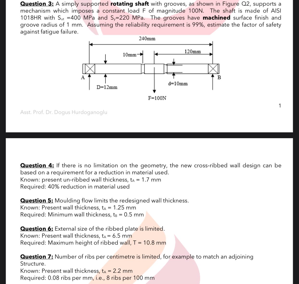
Question: Question 3 : A simply supported rotating shaft with grooves, as shown in Figure Q 2 , supports a mechanism which imposes a constant load
Question : A simply supported rotating shaft with grooves, as shown in Figure Q supports a mechanism which imposes a constant load of magnitude N The shaft is made of AISI HR with MPa and MPa. The grooves have machined surface finish and groove radius of mm Assuming the reliability requirement is estimate the factor of safety against fatigue failure.
Asst. Prof. Dr Dogus Hurdoganoglu
Question : If there is no limitation on the geometry, the new crossribbed wall design can be based on a requirement for a reduction in material used.
Known: present unribbed wall thickness,
Required: reduction in material used
Question : Moulding flow limits the redesigned wall thickness.
Known: Present wall thickness,
Required: Minimum wall thickness,
Question : External size of the ribbed plate is limited
Known: Present wall thickness,
Required: Maximum height of ribbed wall,
Question : Number of ribs per centimetre is limited for example to match an adjoining Structure.
Known: Present wall thickness,
Required: ribs per mm ie ribs per mm
Step by Step Solution
There are 3 Steps involved in it
1 Expert Approved Answer
Step: 1 Unlock

Question Has Been Solved by an Expert!
Get step-by-step solutions from verified subject matter experts
Step: 2 Unlock
Step: 3 Unlock