

Question: Question 3 : Figure 1 - 2 A shaft as a part of a drive for an automated transfer system in a metal stamping plant
Question :
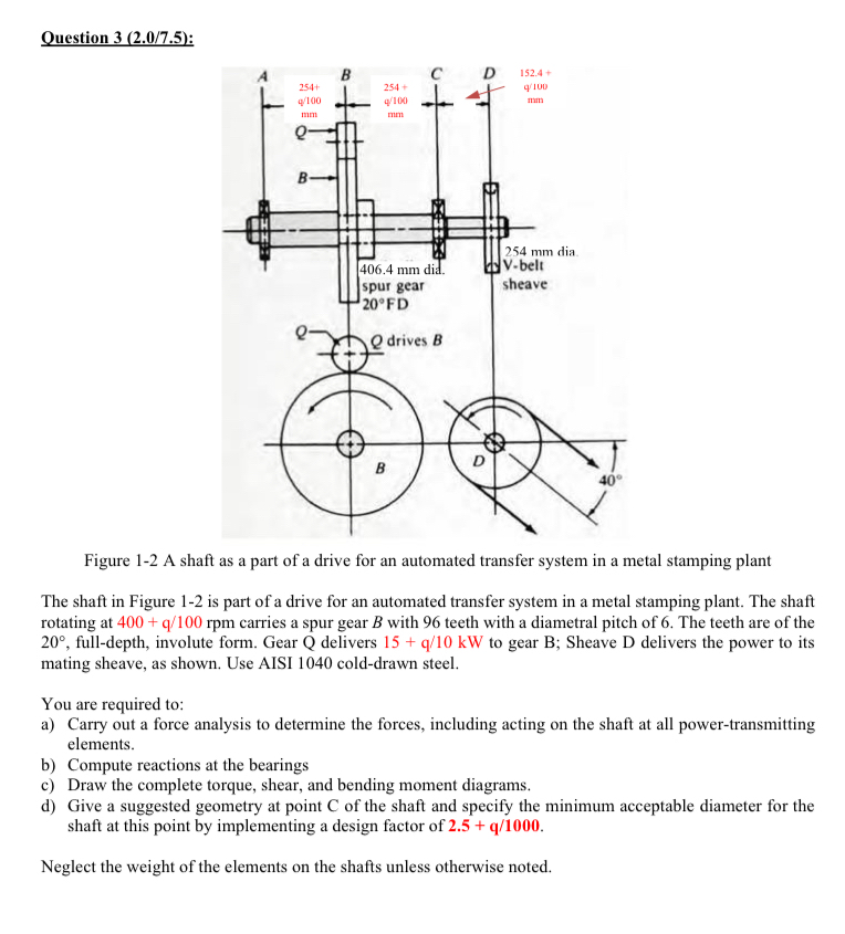
Figure A shaft as a part of a drive for an automated transfer system in a metal stamping plant
The shaft in Figure is part of a drive for an automated transfer system in a metal stamping plant. The shaft rotating at carries a spur gear with teeth with a diametral pitch of The teeth are of the fulldepth, involute form. Gear Q delivers to gear B; Sheave D delivers the power to its mating sheave, as shown. Use AISI colddrawn steel.
You are required to:
a Carry out a force analysis to determine the forces, including acting on the shaft at all powertransmitting elements.
b Compute reactions at the bearings
c Draw the complete torque, shear, and bending moment diagrams.
d Give a suggested geometry at point C of the shaft and specify the minimum acceptable diameter for the shaft at this point by implementing a design factor of
Neglect the weight of the elements on the shafts unless otherwise noted.
q
Step by Step Solution
There are 3 Steps involved in it
1 Expert Approved Answer
Step: 1 Unlock

Question Has Been Solved by an Expert!
Get step-by-step solutions from verified subject matter experts
Step: 2 Unlock
Step: 3 Unlock