

Question: Question 4 ( 2 5 marks ) For the beam shown in Figure Q 4 , the externally applied loads can be defined as:
Question marks
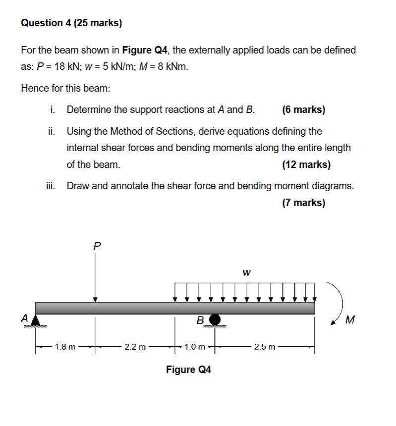
For the beam shown in Figure Q the externally applied loads can be defined as: PmathrmkN ; wmathrmkNmathrmm ; MmathrmkNm
Hence for this beam:
i Determine the support reactions at A and B
ii Using the Method of Sections, derive equations defining the internal shear forces and bending moments along the entire length of the beam.
iii. Draw and annotate the shear force and bending moment diagrams.
marks
Figure Q
Step by Step Solution
There are 3 Steps involved in it
1 Expert Approved Answer
Step: 1 Unlock

Question Has Been Solved by an Expert!
Get step-by-step solutions from verified subject matter experts
Step: 2 Unlock
Step: 3 Unlock