

Question: Consider the liquid-level control system shown in Fig. P12-4. The tanks are noninteracting. The following information is known: The resistances on the tanks are

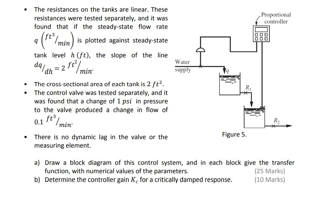
Consider the liquid-level control system shown in Fig. P12-4. The tanks are noninteracting. The following information is known: The resistances on the tanks are linear. These Proportional resistances were tested separately, and it was found that if the steady-state flow rate controller in is plotted against steady-state tank level h (ft), the slope the line = 2 ft/ min Water da dh supply The cross-sectional area of each tank is 2 ft2. The control valve was tested separately, and it was found that a change of 1 psi in pressure to the valve produced a change in flow of 0.1 ft /min: R2 There is no dynamic lag in the valve or the Figure 5. measuring element. a) Draw a block diagram of this control system, and in each block give the transfer function, with numerical values of the parameters. b) Determine the controller gain K. for a critically damped response. (25 Marks) (10 Marks)
Step by Step Solution
3.50 Rating (147 Votes )
There are 3 Steps involved in it

Get step-by-step solutions from verified subject matter experts