

Question: Question 4 4 . Consider the circuit shown in Figure 4 . 1 . The source, widehat ( V i n ) , is a
Question
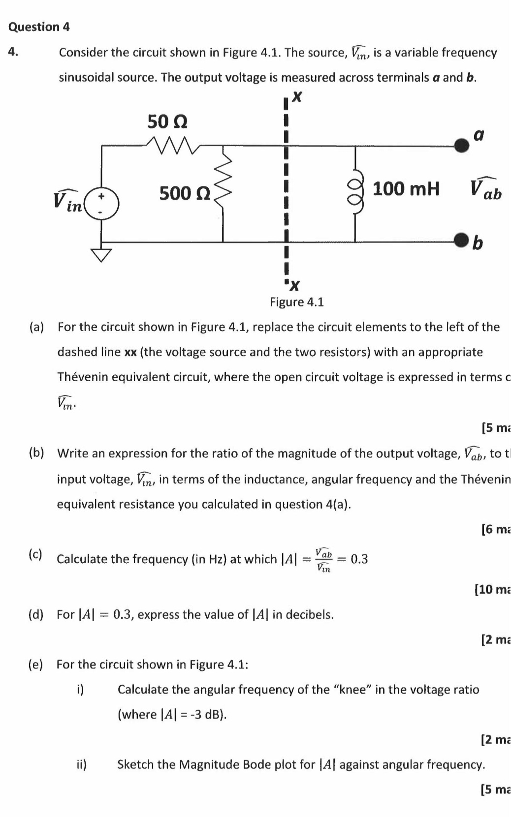
Consider the circuit shown in Figure The source, widehat is a variable frequency sinusoidal source. The output voltage is measured across terminals a and
a For the circuit shown in Figure replace the circuit elements to the left of the dashed line the voltage source and the two resistors with an appropriate Thvenin equivalent circuit, where the open circuit voltage is expressed in terms c widehat
b Write an expression for the ratio of the magnitude of the output voltage, widehat to input voltage, widehat in terms of the inductance, angular frequency and the Thvenin equivalent resistance you calculated in question a
mi
c Calculate the frequency in Hz at which
ma
d For express the value of in decibels.
me
e For the circuit shown in Figure :
i Calculate the angular frequency of the "knee" in the voltage ratio where
ma
ii Sketch the Magnitude Bode plot for against angular frequency.
marks
Step by Step Solution
There are 3 Steps involved in it
1 Expert Approved Answer
Step: 1 Unlock

Question Has Been Solved by an Expert!
Get step-by-step solutions from verified subject matter experts
Step: 2 Unlock
Step: 3 Unlock