

Question: Question 4: Sequential Logic Circuit Timing Diagram (7 points) The following circuit is called a Johnson counter. It has a number of uses in digital
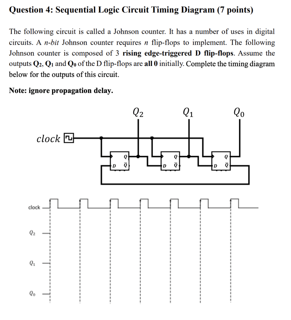
Question 4: Sequential Logic Circuit Timing Diagram (7 points) The following circuit is called a Johnson counter. It has a number of uses in digital circuits. A n-bit Johnson counter requires n flip-flops to implement. The following Johnson counter is composed of 3 rising edge-triggered D flip-flops. Assume the outputs Q2,Q1 and Q0 of the D flip-flops are all 0 initially. Complete the timing diagram below for the outputs of this circuit. Note: ignore propagation delay
Step by Step Solution
There are 3 Steps involved in it
1 Expert Approved Answer
Step: 1 Unlock

Question Has Been Solved by an Expert!
Get step-by-step solutions from verified subject matter experts
Step: 2 Unlock
Step: 3 Unlock