

Question: Question 5 ( 1 5 points ) Consider the system described below and answer the subsequent question. System Configuration: Inputs: SW 1 and SW 2
Question points
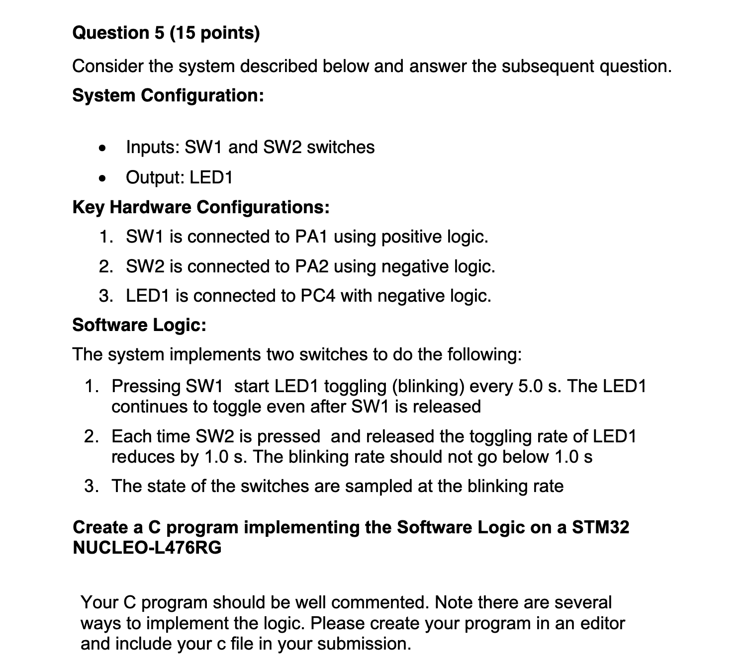
Consider the system described below and answer the subsequent question.
System Configuration:
Inputs: SW and SW switches
Output: LED
Key Hardware Configurations:
SW is connected to PA using positive logic.
SW is connected to PA using negative logic.
LED is connected to PC with negative logic.
Software Logic:
The system implements two switches to do the following:
Pressing SW start LED toggling blinking every The LED
continues to toggle even after SW is released
Each time SW is pressed and released the toggling rate of LED
reduces by The blinking rate should not go below
The state of the switches are sampled at the blinking rate
Create a C program implementing the Software Logic on a STM
NUCLEOLRG
Your C program should be well commented. Note there are several
ways to implement the logic. Please create your program in an editor
and include your c file in your submission.
Step by Step Solution
There are 3 Steps involved in it
1 Expert Approved Answer
Step: 1 Unlock

Question Has Been Solved by an Expert!
Get step-by-step solutions from verified subject matter experts
Step: 2 Unlock
Step: 3 Unlock