

Question: QUESTION 5 Using the components available in the practice kit, assemble the circuit shown in the figure. The component values are R = 5 6
QUESTION
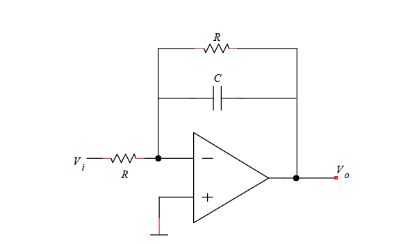
Using the components available in the practice kit, assemble the circuit shown in the figure. The component values are R and C nF and the operational amplifier power supply voltages are V and V Use a sinusoidal input signal with an amplitude of V and vary the frequency as indicated in each option.
Reason properly, based on the measurements you take, whether the following statements are true or not: a
The circuit functions as a lowpass filter, attenuating highfrequency signals and allowing lowfrequency signals to pass through.
b
At an input frequency of Hz the output will show an amplitude similar to that of the input signal, with a phase difference between the two signals.
c
For input frequencies of Hz kHz kHz kHz kHz and up to kHz the amplitude of the output signal will progressively decrease as the frequency increases, showing an attenuation trend.
d
In a graph of the quotient between the output and input amplitudes as a function of frequency, the ratio between the two magnitudes tends to be less than for frequencies above kHz
Step by Step Solution
There are 3 Steps involved in it
1 Expert Approved Answer
Step: 1 Unlock

Question Has Been Solved by an Expert!
Get step-by-step solutions from verified subject matter experts
Step: 2 Unlock
Step: 3 Unlock