

Question: Question 7 Using basic 2-input, single output logic gates, implement the following one bit adder. A B CIN Y cout AB 0 0 0 1
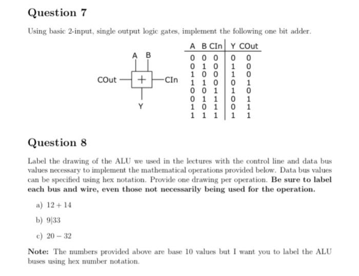
Question 7 Using basic 2-input, single output logic gates, implement the following one bit adder. A B CIN Y cout AB 0 0 0 1 0 1 0 1 0 0 1 0 cout -Cin 1 1 0 0 1 0 0 1 1 0 0 1 1 0 1 Y 1 0 1 0 1 1 1 1 1 1 + Question 8 Label the drawing of the ALU we used in the lectures with the control line and data bus values necessary to implement the mathematical operations provided below. Data bus values can be specified using hex notation. Provide one drawing per operation. Be sure to label each bus and wire, even those not necessarily being used for the operation. a) 12 + 14 b) 933 c) 20 - 32 Note: The mmbers provided above are base 10 values but I want you to label the ALU buses using hex number notation
Step by Step Solution
There are 3 Steps involved in it

Get step-by-step solutions from verified subject matter experts