

Question: Question # 9 The voltage source V in the circuit shown in Fig. 9 is set to 1 0 V . The current I is
Question #
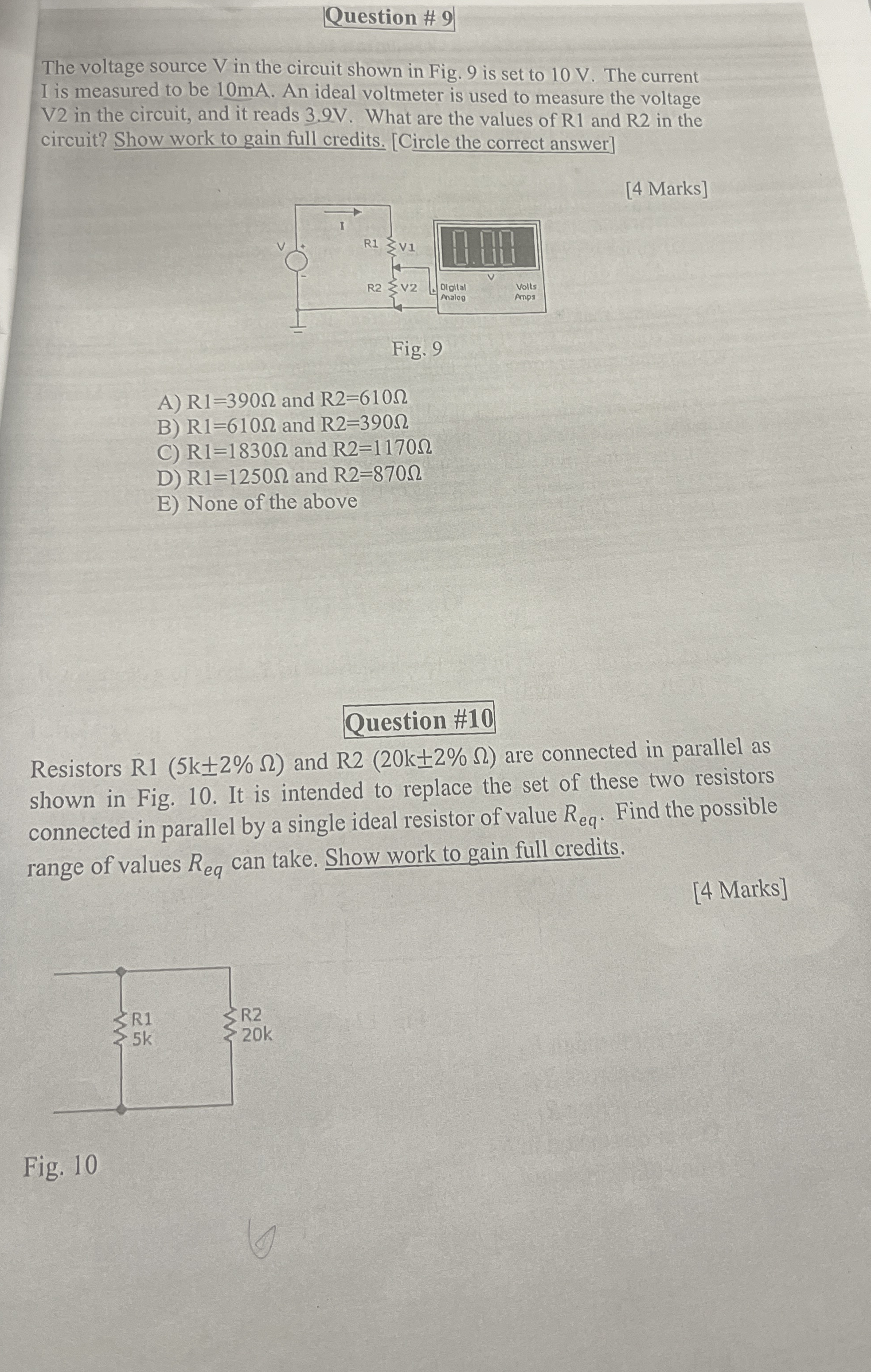
The voltage source V in the circuit shown in Fig. is set to V The current I is measured to be mA An ideal voltmeter is used to measure the voltage V in the circuit, and it reads V What are the values of R and R in the circuit? Show work to gain full credits. Circle the correct answer
Marks
A and
B and
C and
D and
E None of the above
Question #
Resistors R and R are connected in parallel as shown in Fig. It is intended to replace the set of these two resistors connected in parallel by a single ideal resistor of value Find the possible range of values can take. Show work to gain full credits.
Marks
Fig.
Step by Step Solution
There are 3 Steps involved in it
1 Expert Approved Answer
Step: 1 Unlock

Question Has Been Solved by an Expert!
Get step-by-step solutions from verified subject matter experts
Step: 2 Unlock
Step: 3 Unlock