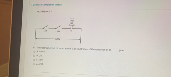
Question: Question Completion Status: QUESTION 37 XI X2 120V gate. 37. The electrical circuit pictured above, is an illustration of the operation of an A NAND

Question Completion Status: QUESTION 37 XI X2
Question Completion Status: QUESTION 37 XI X2 120V gate. 37. The electrical circuit pictured above, is an illustration of the operation of an A NAND B.OR C. NOT D. AND QUESTION 38 X1 38. The truth table for the following circuit logic is: A Inputs Output X1 X2 Y 0 1 0 0 1 1 1 0 0 0 0 1 B. Inputs Output X1 X2 Y 0 0 1 1 1 1 1 1 0 1 Click Save and Submit to QUESTION 39 39. In a the various components are displayed along horizontal lines connected on either end to two vertical rails. A. logic circuit diagram B. function ladder C. ladder logic diagram D. either A or QUESTION 40 40. The following symbol represents a: A normally open switch B. normally closed switch Coutput load D. Counter Click Save and Submit to save and submit. Chick Save All Answers to save all answers Save Ad Answe

Step by Step Solution

There are 3 Steps involved in it

1 Expert Approved Answer
Step: 1 Unlock blur-text-image
Question Has Been Solved by an Expert!

Get step-by-step solutions from verified subject matter experts

Step: 2 Unlock
Step: 3 Unlock

Students Have Also Explored These Related General Management Questions!